Background
For vessels in services where there is a potential for cracking, post-weld heat treatment (PWHT) may be required. In those cases, when a component is replaced in the field, the repair would require a local PWHT of the new weld(s). The crews follow a procedure built around the recommendations of WRC 452: hold the soak temperature for the required time and document the thermocouple traces. On paper, the weld has been stress-relieved, but the key question remains unanswered: by how much?
That question is especially important when the original damage mechanism was driven by residual stress. For instance, a vessel that cracked from chloride stress cracking (CSC) will crack again if the replacement weld is left with a residual stress field above the environmental threshold. A local PWHT that satisfied its procedural requirements but only modestly relaxed the weld can give an owner false confidence that the underlying threat has been addressed.
To quantify this, a coupled welding and PWHT finite element simulation of an actual repair scenario was built, and the resulting residual stresses were compared to those expected from a furnace treatment. The results are a useful caution for anyone who specifies, performs, or takes credit for local PWHT without any additional considerations. Note that this is a single case study and conclusions from this article should not be blanketly applied to all cases.
A Gap in the FFS Standard
Field PWHT frequently occurs hand-in-hand with fitness-for-service (FFS) work, and API 579 Annex 9D provides reference residual stress solutions for common welding geometries in the as-welded and PWHT condition (uniformly done in a furnace). For a carbon steel, such as SA-516-70, the standard suggests that a uniform PWHT reduces the residual stress perpendicular to the weld seam to roughly 0.30 times the estimated actual yield strength and the stress parallel to the seam to roughly 0.20 times yield. Expressing those components as an equivalent (Mises) stress yields a target of about 12.7 ksi, which is on the order of 0.26 times the yield strength of this material.
The gap is that Annex 9D does not provide an equivalent set of reduced values for local PWHT since it leaves it to the practitioner to determine an appropriate residual stress for a locally heat-treated weld. In the absence of explicit weld modeling, the practitioner cannot be certain if a local procedure performed in the field to current accepted industry practice delivers the same residual stress reduction as that done in a furnace and thus if furnace values can simply be used. This case study was performed to test that assumption rather than presume it.
What is WRC 452?
Current industry practice for local PWHT leans heavily on WRC 452. First published in 2000 and built on earlier American Welding Society (AWS)-recommended practices for local heating of welds in piping, it has become one of the most referenced documents in the field. Its recommendations form the basis of the local PWHT requirements in ASME VIII-1 [3], the National Board Inspection Code (NBIC), and a range of API standards including API 579, API TR 934-B, and API RPs 934-C, 941, and 945.
WRC 452 is sometimes treated as an “unofficial” code; while there are several follow-up bulletins on the same subject, those do not see the same readership. More importantly, compliance with WRC 452 does not guarantee complete relaxation of a weld residual stress field. The recommended practice allows meaningful latitude in the sizing of the soak, heating, and gradient control bands, and the interaction between the creep relaxation that occurs in the early heating phase and the additional creep strain generated outside the weld region is complex.
It is worth noting that there is now a 2nd edition of WRC 452 (published June 2026) reflecting advances in the understanding of local PWHT. At the time of this case study, this 2nd edition had not yet been published, so all references to WRC 452 herein are based on the 1st edition.
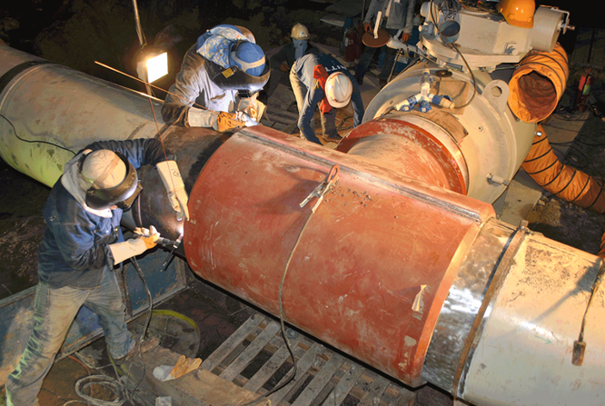
The Case Study: A Cracked Fractionator Head
The component analyzed was the top head of a fractionator tower built in 1989 to ASME VIII-1, fabricated from SA-516-70 carbon steel, with a shell having an inside diameter of 144 inches, nominal thickness of 0.625 inches, and a 2:1 semi-elliptical head with a nominal thickness of 0.5 inches. The head had experienced CSC damage and the replacement of the head and local PWHT of the new head-to-shell weld would occur onsite. The main concern was if the repair itself would introduce a residual stress field that puts the new weld at risk of the same cracking.
Since there is no industry-accepted threshold stress for CSC, a literature review [4-6] suggests that CSC can initiate in carbon steel at a threshold stress of roughly 80% of room-temperature yield [5], and in highly aggressive conditions, the threshold can fall to as low as 40% of yield [6]. Table 1 shows what those bounds mean in practice for SA-516-70, alongside the furnace PWHT target derived from API 579 Annex 9D. Note that the furnace-PWHT target derived from Annex 9D sits below the aggressive lower bound, which is exactly why a furnace-PWHT result would be reassuring.
Table 1: CSC Threshold Stress Ranges
| Condition | Threshold Stress (% of Yield) | Threshold Stress for SA-516-70 (ksi) |
| Approximate Upper Bound for CSC | 80% | 38.4 ksi |
| Approximate Lower Bound for CSC | 40% | 19.2 ksi |
| Furnace PWHT target (API 579 Annex 9D) | ~26% | ~12.7 ksi |
FEA Model: Explicit Weld Simulation and PWHT Simulation
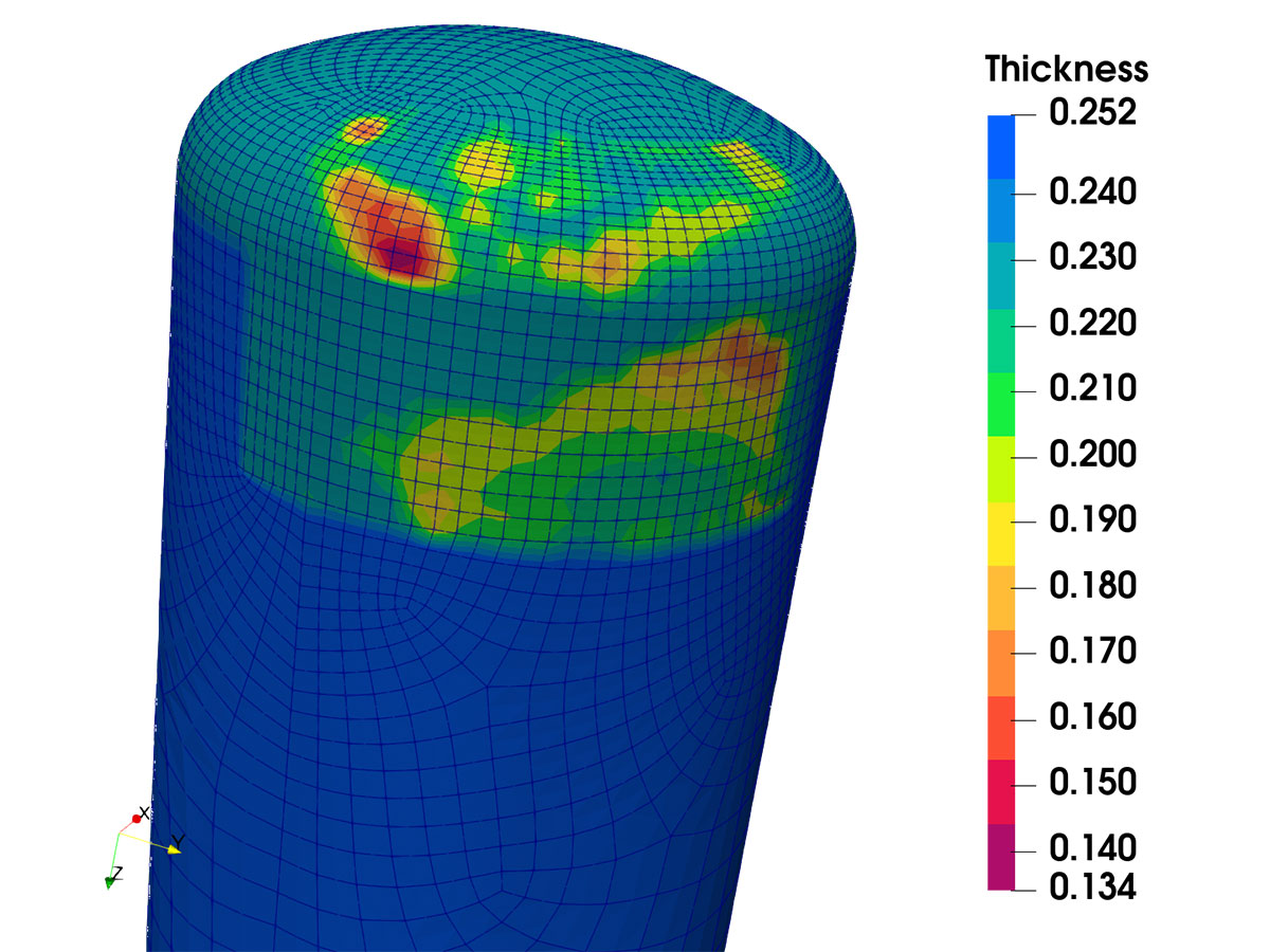
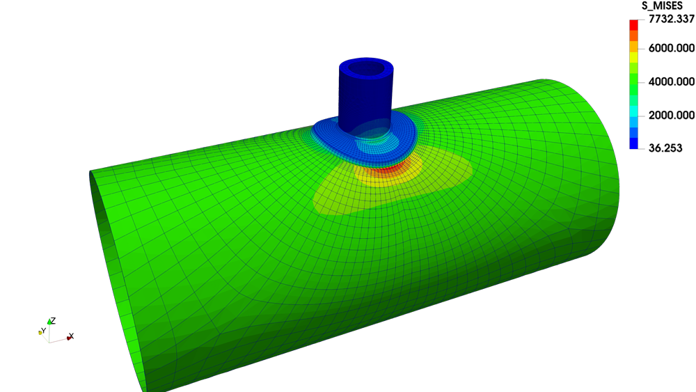
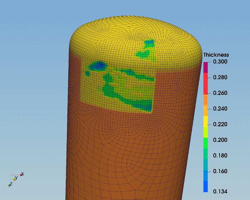
The analysis was performed in two coupled stages in ABAQUS. The first stage simulated the multi-pass shielded metal arc weld itself — six interior beads and four exterior beads deposited after back-gouging a single-vee preparation to an approximate double-vee — using a moving Goldak heat source and temperature-dependent material properties. Yield, tensile, and elastic modulus data for SA-516-70 were taken from ASME Section II Part D [7] up to the limits of the published data and extended to elevated temperatures using ASME STP-PT-096 [8], WRC Bulletin 503 [9], and available literature [10]. The output of this stage was the as-welded residual stress field.
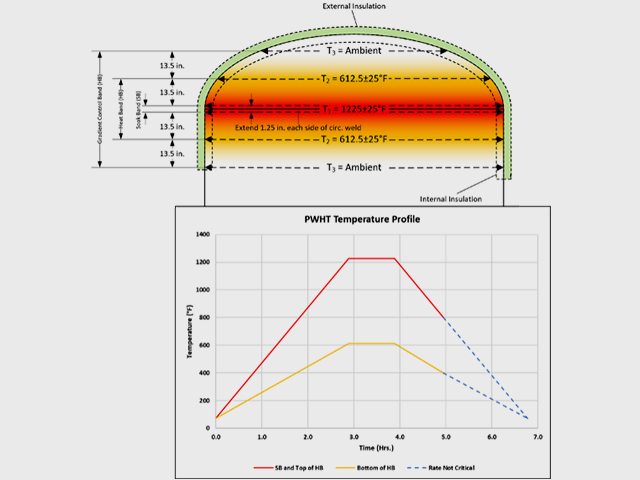
The second stage mapped the as-welded stress field and simulated the local heat treatment as a transient thermal and mechanical analysis. The PWHT procedure followed the minimum requirements for local full-circumferential band heating in ASME VIII-1 and WRC 452: a soak band held at 1225°F (662.78°C) and extending a distance of 2t on either side of the weld centerline, a heating band at roughly half the soak temperature, and a gradient control band sized outward from there, all with a maximum ramp rate of 400°F/hr (204.44°C/hr). External insulation was not explicitly modeled, but equivalent film coefficients were applied for the insulated and uninsulated surfaces.
The choice of creep model is worth emphasizing. Stress relaxation during PWHT is fundamentally a creep process, so the result depends entirely on how creep is represented. A Bailey-Norton time-hardening model was used here [11] because it has the capacity to represent primary and secondary creep, which is the regime that governs short-duration heat treatment. In contrast, an Omega-type model is oriented toward tertiary creep and can be difficult to tune in a high-temperature situation with short time constraints (in this work, benchmarking confirmed that the Bailey-Norton secondary creep results are consistent with Omega average properties).
The Result: Local PWHT Falls Short in Weld Residual Stress Reduction
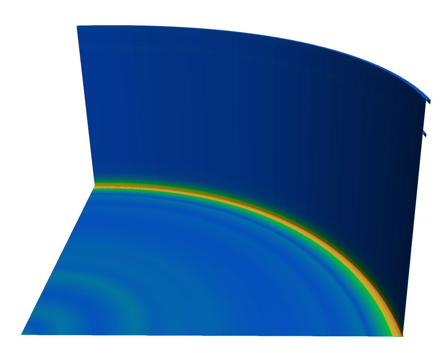
A furnace PWHT, when simulated the same way, produced through-wall residual stresses that align closely with the reduced values in API 579 Annex 9D — confirming both the model and the standard. However, the local PWHT performed to WRC 452 did not provide similar reductions — along the through-thickness paths examined at the center and edges of the weld, the equivalent residual stress after local treatment remained substantially elevated relative to the furnace case and stayed within the theoretical CSC threshold band. In other words, in this particular example, a weld treated by a procedure that fully complied with WRC 452 still carried enough residual stress to remain at risk of the very cracking mechanism the PWHT was intended to eliminate.
The physical reason for the PWHT-induced residual stress traces back to the non-linear axial temperature gradient produced by local band heating. Unlike a furnace, where the entire component reaches a uniform soak temperature and relaxes together, local heating creates a non-linear temperature profile along the shell which results in thermally induced stresses [12].
The baseline WRC 452 local PWHT (purple) sits at or above the 80% yield CSC threshold (38.4 ksi), while the furnace bakeout (yellow) lands on the API 579 Annex 9D furnace value (~12.7 ksi). Revised and optimized local procedures (red and black) improve the result but do not reach furnace levels.
Potential Options for Reducing Weld Residual Stress
Having analyzed the baseline local PWHT procedure in accordance with WRC 452, several options for improvement were subsequently explored: widening the soak band, increasing the heating band temperatures, extending the hold time, slowing the ramp rates, and increasing insulation thickness.
Tracking creep strain against time through the full PWHT cycle revealed that the majority of stress-relieving creep strain accumulates during the heating and cooling ramps, not during the hold at soak temperature. Consequently, slowing the ramp rate from 400°F/hr (204.44°C/hr) to 200°F/hr (93.33°C/hr) was the most effective single change for reducing the final residual stress, more so than widening the soak band. While widening the band helped, even combining a wider band with a higher heating-band-to-soak-band temperature ratio did not bring the residual stress down to furnace levels.
The practical takeaway is that residual stress relaxation is governed by how much creep strain is generated, and creep strain is accumulated principally when the temperature is ramping up or down, not during soak. A procedure designed for maximum stress relief should treat the ramp schedule as a primary design variable rather than an afterthought, while recognizing that even the results of an optimized local procedure may not match that of a furnace heat treatment.
Most stress-relieving creep strain accumulates during the ramps rather than during the hold at soak temperature.
Implications for Field Local PWHT
The reduced residual stress values in API 579 Annex 9D are appropriate for furnace PWHT and should not be applied to local PWHT scenarios without justification. Documentation showing that a local PWHT was performed “per WRC 452” establishes that a recognized procedure was followed; it does not establish a particular residual stress magnitude, however, and in an FFS assessment, the residual stress assumption drives the result. Where the original or anticipated damage mechanism is sensitive to residual stress (e.g., environmental cracking, fatigue, or brittle fracture), a more rigorous basis for the residual stress is warranted, whether through explicit coupled weld-and-PWHT simulation or a conservative bounding estimate.
Modern simulation has made this type of analysis far more accessible than it once was, and offers a more accurate, scenario-specific picture of residual stress than generic reference solutions can provide. A comprehensive PWHT analysis needs to account for the as-welded residual stress state, the non-linear temperature gradients inherent to local heating, and the creep behavior that drives relaxation. Geometry also plays an important role in that adjacent structural discontinuities and high-restraint configurations can defeat a procedure that would otherwise be adequate, and optimizing local PWHT around such features remains an area needing further work.
Conclusion
Local PWHT is a routine, code-sanctioned, and often unavoidable part of field repair, and WRC 452 has served the industry well for more than two decades as the practical basis for it. A coupled welding and PWHT simulation of a head-to-shell weld of a fractionator shows that a local PWHT procedure can leave residual stresses well above the furnace-equivalent values from API 579 Annex 9D and inside the band where CSC can initiate. It also suggests that one of the most powerful levers for improvement is decreasing the ramp rate since that is where the stress-relieving creep strain is generated.
How Equity Can Help
Equity Engineering’s Mechanical & Structural Engineering team routinely performs PWHT simulations to quantify residual stress for FFS assessments and field repair planning. Our capabilities in this area include:
- Finite element weld simulation for in-service and replacement welds to quantify residual stresses after welding
- Local and furnace PWHT modeling to quantify residual stresses after PWHT
- PWHT procedure optimization (varying levers such as ramp rates, SB/HB/GCB sizing, etc.) to reduce residual stress.
- Support for field repair strategies on equipment subject to environmental cracking and other residual-stress-driven damage mechanisms
- Review of PWHT layouts
With deep expertise in advanced stress analysis and the codes and standards that govern PWHT, Equity is well-positioned to help owners and operators make repair and assessment decisions.
References
- McEnerney, J.W., and Dong, P., Recommended Practices for Local Heating of Welds in Pressure Vessels, WRC Bulletin 452, Welding Research Council, Inc., New York, NY, 2000.
- API 579-1/ASME FFS-1, Fitness-For-Service, 4th Edition, The American Petroleum Institute, 2021.
- 2025 ASME Boiler & Pressure Vessel Code, Section VIII, Division 1, Rules for Construction of Pressure Vessels, ASME, New York, NY.
- Alhajri, R., Liu, S., Yu, Z., and Andreassen, M.J., “The Need for Postweld Heat Treatment for Applications Involving Stress Corrosion Cracking,” Welding Journal, 2017, pp. 451–466.
- Jones, R., and Ricker, R., Stress-Corrosion Cracking: Material Performance and Evaluation, ASM International, Materials Park, Ohio, 1992, pp. 1–38.
- Fessler, R.R., and Barlo, T.J., “Threshold-Stress Determination Using Tapered Specimens and Cyclic Stresses,” Environment-Sensitive Fracture: Evaluation and Comparison of Test Methods, ASTM STP 821, S.W. Dean, E.N. Pugh, and G.M. Ugiansky, Eds., American Society for Testing and Materials, Philadelphia, 1984, pp. 368–382.
- 2025 ASME Boiler & Pressure Vessel Code, Section II, Part D — Properties (Customary), ASME, New York, NY.
- ASME Standards Technology, Elevated Temperature Material Property Compilation for Design-By-Analysis, STP-PT-096, New York, NY, 2022.
- Osage, D.A., et al., Compendium of Temperature-Dependent Physical Properties for Pressure Vessel, Piping and Tankage, WRC Bulletin 503, Welding Research Council, Inc., New York, NY, 2019.
- Gowda, B.C., Tensile Properties of SA-516, Grade 55, Steel in the Temperature Range of 25°–927°C, 1978.
- Penny, R.K., and Marriott, D.L., Design for Creep, Second Edition, Chapman & Hall, 1995.
- Lee, C.W., “Thermoelastic Stresses in Thick-Walled Cylinders Under Axial Temperature Gradient,” Journal of Applied Mechanics, ASME, 1966, pp. 467–469.