1 Overview
1.1 TANKSETT Module
The TANKSETT analysis module is used to evaluate the effects of bottom settlement in above ground storage tanks per Annex B of API 653. Three types of settlement are available for analysis: shell settlement, edge settlement, and localized bottom settlement. Shell settlement is the sum of uniform and differential vertical displacement of the tank shell about a plane of rigid tilt, occurring around the circumference of the tank. Edge settlement is the vertical displacement of the tank bottom from the periphery of the tank shell. Localized bottom settlement is vertical displacement of a local region of the tank bottom away from the tank shell. By implementing procedures described in API 653 Annex B, TANKSETT can be used to determine the damage margin for each type of settlement. The type of analysis conducted by TANKSETT is specified by setting the value of SETTANAL equal to SHELL, EDGE, or BULGE.
1.2 Module Usage
TANKSETT is not a standalone analysis module; rather, it is a child module of the SAGE TANK analysis module. For additional description of tanks that are able to be analyzed by TANK and TANKSETT, see Section 2.1 of the TANK user manual.
2 Specifying the Geometry
A tank analyzed using the TANKSETT module is assumed to be welded but otherwise can be any valid API 650 design. The shell settlement procedures base permissible settlement on the tank’s roof configuration, and the type of roof (ROOFTYPE = OPEN or FIXED) must be input. The procedures implemented by TANKSETT require values for tank diameter (TDIA) and tank height (THEIGHT).
3 Specifying the Materials of Construction
The tank shell material’s Young’s modulus (EY) and yield stress (SY) are required to perform shell settlement evaluation and input. From the specification, the Young’s modulus and yield stress are determined based on the API 650. The physical properties may be manually overwritten with user-defined values. If both a material specification and user-defined properties are input, the user-defined properties will supersede the determined Code material properties.
4 Specifying the Applied Loads
Loading in the TANKSETT module consists of settlement displacements which depend on the type of settlement being evaluated (shell, edge or localized bottom). The type and measurement of these settlement displacements are further described in Section 5.
5 Assessment Method
5.1 Tank Shell Settlement
5.1.1 Measurement Requirements
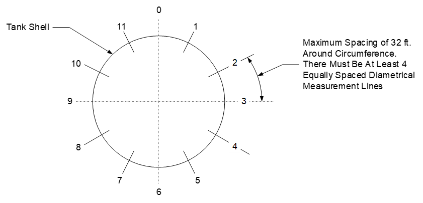
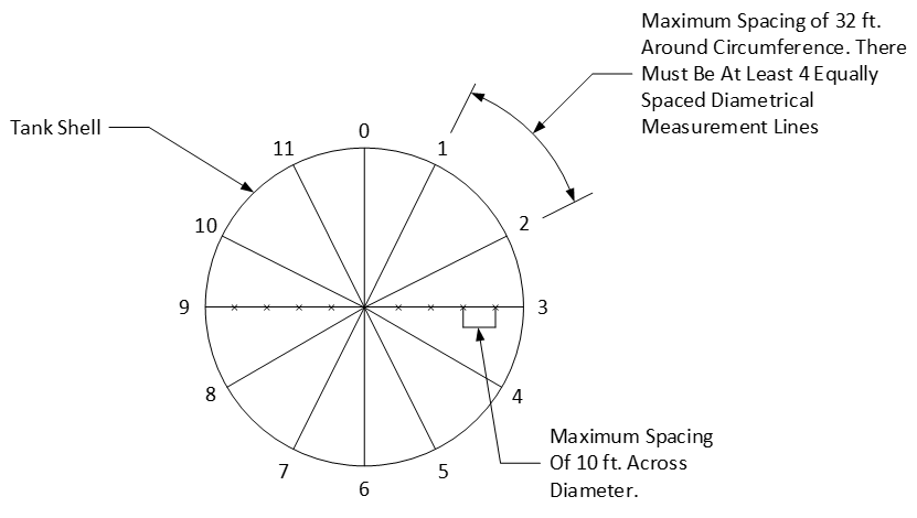
To calculate the damage margin associated with shell settlement, measurements of the total shell settlement at various locations around the perimeter of the tank must be input. The location of each measurement must also be specified in ascending order in degrees. In compliance with API 653 Annex B, there must be at least 8 uniformly spaced measurements entered, and the maximum allowable circumferential spacing between two adjacent measurements is 32 feet (see Figures 1 and 2).
5.1.2 Assessment Techniques
As outlined in Section B.2.2.4 of API 653 Annex B, a given set of shell settlement data is first categorized by how closely the data can be fit to an optimum cosine curve.
(1)
with a nonlinear regression algorithm. After finding the values of a, b, and c that optimize the fit of Elevpred to the data, the value of R2 is computed with:
(2)
where,
(3)
(4)
If R2 is greater than 0.9, then the optimum cosine curve type is considered valid. Otherwise, the settlement is said to be localized or arbitrary. For the optimum cosine curve, the differential shell settlement at point θi is determined by subtracting Equation (1) evaluated at θi from the total shell settlement measurement Ui at θi.
5.1.3 Optimal Cosine Curve Settlement
TANKSETT calculates vertical displacement and the maximum allowable displacement at each measurement location with:
(5)
(6)
where L is the arc length between Ui and Ui-1 or Ui+1 in feet, whichever is smaller. Then the damage margin at measurement location i is then calculated with,
(7)
Finally, the overall shell damage margin for the tank is set equal to:
(8)
5.1.4 Arbitrary or Localized Settlement
TANKSETT uses the geometric approach from API 653 Annex B, Sections 2.2.5.1 and 3.2.2, with refinements. Note that this analysis is not valid for the following:
- Any fixed roof tank with a diameter greater than 180 feet.
- Any open roof tank with a diameter greater than 300 feet.
- Any tank that is carbon steel or stainless steel.
To analyze the effect of shell settlement in any of the cases above, a detailed stress analysis is recommended.
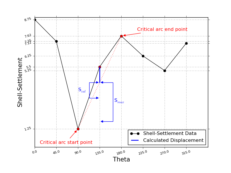
The shell settlement data U is plotted versus θ on the x-y coordinate plane. For each data point (θi, Ui) in a size n set of shell settlement data points, the analysis draws the straight lines connecting the current data point (denoted Ustart) and the data points at least two readings away (denoted Uend). The length of an arc beginning at (θstart, Ustart) and ending at (θend, Uend) is calculated using the formula:
(9)
(10)
(11)
Then the maximum allowable displacement Smax at (θstart, Ustart) is determined using:
(12)
(13)
5.1.5 Radial Displacement
Out-of-roundness at the top of a tank is a consequence of differential shell settlement, caused by uneven ground underneath the tank. For radial displacement to be present in a tank, there must be a sufficient amount of differential shell settlement. That is, Equation (2) in Section 5.1.2 must be less than 98% (implying that 98% of the shell settlement can be explained by uniform shell settlement and/or planar tilt, and differential shell settlement is negligible).
If sufficient differential shell settlement is present, the analysis begins by finding the best-fit curve to the differential shell settlement data using the Levenberg-Marquardt algorithm for nonlinear regression. The differential shell settlement model is based on the truncated Fourier series.
(14)
This model is based on the research findings in Malik’s “Ovalization of Cylindrical Tanks as a Result of Foundation Settlement.” To minimize the oscillations of this curve, the analysis initially assumes the minimum number of two parameters a2 and b2; if this model does not fit the data by at least 98%, the analysis increases the number of parameters by two and repeats the regression. This process is repeated until it finds the minimum number and values of parameters an and bn that fit the curve to the data at least 98%. Then radial displacement at θ is calculated with the equation:
(15)
Next, the analysis determines the minimum and maximum magnitudes of radial displacement and their location.
5.1.6 Vapor Escape Areas
For tanks with floating roofs, out-of-roundness can distort the tank in such a way that gaps form between the tank and the roof. Toxic vapor can escape from these gaps; the amount of vapor escape is, in part, dependent on the surface area of the gaps. Equation (12) models the radial displacement at the top of the tank; by integrating the function where it is positive, the analysis can determine the size of the open gaps. The analysis first finds all the roots of Equation (12) on the interval [0.00, 360.00] using an iterative secant method routine. Next, it checks whether the function is positive on each of the individual subintervals between the roots and the function endpoints. If a subinterval is found to have positive integration between points a and b, the routine calculates the polar area (see Figure 8).
(16)
Finally, the analysis sums the individual areas of vapor escape to find the total vapor escape area.
5.1.7 Shell Settlement Results
TANKSETT reports the values of a, b, c, and R2 from Equations (1) and (2) to illustrate which type of shell settlement a tank is being subjected to. Two summary tables are produced: one that includes the value of vertical displacement, maximum allowable displacement, and damage margin at each measurement location, and another that includes the sizes of uniform shell settlement, planar tilt, and differential shell settlement at a given θ. The value of DMshell from Equation (7) is also displayed. For tanks that meet the criteria outlined in Section 2.2.5, TANKSETT reports a summary table containing Equation (11), its first and second derivatives, and Equation (12), all evaluated at θ. It also reports the minimum and maximum values of radial displacement and where they occur. For tanks that additionally meet the criteria outlined in Section 2.2.6, TANKSETT reports the starting location, ending location, and magnitude of each individual area of vapor escape, as well as the total area of vapor escape.
5.2 Tank Edge Settlement at the Shell
5.2.1 Measurement Requirements
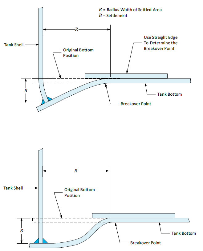
To evaluate the effects of edge settlement, the radial width of each edge settled region considered must be input. Along each radius of edge settlement, at least four values must be provided, and at each reading, the angle between the shell and the bottom lap weld must be specified (in degrees) (see Figure 3).
5.2.2 Assessment Technique
When SETTANAL is set equal to EDGE, TANKSETT implements an edge settlement analysis using the measurements of the edge settlement geometry provided by the user. The analysis is performed in accordance with B.3.4 of API 653. Note that if the radial width of the edge exceeds 6 feet, then a detailed stress analysis should be conducted so that the deformed profile can be examined. See Figures B.11 and B.12 from API 653 Annex B. The maximum allowable edge settlement is determined using an expression which relates the values of the maximum allowable edge settlement parallel at an area parallel to a bottom lap weld and the maximum allowable edge settlement at an area perpendicular to a bottom lap weld. The preceding quantities Bew and Be are are determined with the aid of Figures B.11 and B.12 from API 653 Annex B. Now, the maximum allowable edge settlement at an area at an arbitrary angle to the bottom lap weld a, is computed with:
(17)
The overall edge settlement damage margin for the tank is calculated with:
(18)
5.2.3 Edge Settlement Results
At each data point, the maximum allowable edge settlement for welds parallel, perpendicular, and at the actual angle a to the settlement is reported. The edge settlement damage margin at each data point and the overall edge settlement damage margin for the tank are reported. Note that a damage margin of less than 1.0 does not satisfy the API 653 acceptance criteria.
5.3 Tank Bottom Bulge Settlement
5.3.1 Measurement Requirements
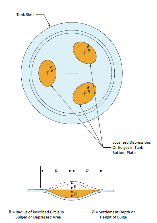
The procedure for evaluating localized bottom settlement requires the radius of an inscribed circle inside an area of bulge or depression (BRAD) and the measured depth of the bulge or depression (BULGED) for any local bottom settlement areas present in the tank (see Figure 4).
5.3.2 Assessment Technique
When SETTANAL=BULGE, TANKSETT calculates the damage margin for local bottom settlement. The maximum allowable bulge or depression displacement in inches at a point i is calculated with the expression:
(19)
Then the local bottom settlement damage margin at measurement i is calculated with:
(20)
Finally, the overall local bottom settlement damage margin for the tank is set equal to:
(21)
5.3.3 Local Bottom Settlement Results
At each data point i, TANKSETT reports the maximum allowable bulge or depression depth and the damage margin at that point. It also reports the overall local bottom settlement damage margin for the tank. Note that a damage margin of less than 1.0 does not satisfy the API 653 acceptance criteria.
6 Nomenclature
B = Maximum allowable edge settlement for areas with a lap weld at an arbitrary angle to the shell.
BB = Maximum height of bulge or depth of local depression, in inches.
Be = Maximum allowable edge settlement for areas with a lap weld approximately parallel to the edge settlement (or perpendicular to the tank shell), or with no welds or butt welds, in inches.
Bdi = Bulge depth measurement at point i.
Bew = Maximum allowable edge settlement for areas with a lap weld approximately perpendicular to the edge settlement (or parallel to the tank shell), in inches.
BR = Radius of an inscribed circle in a bulged area or local depression, in feet.
E = Young’s modulus of the tank material.
Dtank = Tank diameter in feet.
Htank = Height of the tank in feet.
K = Constant for arbitrary shell settlement out-of-plane calculation; see Table 1.
L = Arc length between Ui and Ui-1 or Ui+1 in feet, whichever is smaller.
Rtank = Tank radius in feet.
Si = Vertical out-of-plane displacement due to shell settlement at point i.
Smax = Maximum allowable vertical out-of-plane displacement.
Sy = Yield strength of the tank material.
Syy = Summation of the squares of the differences between the average total settlement and the measured total settlement.
SSE = Sum of the squares of the differences between the measured and predicted total shell settlement.
Ui = Total shell settlement measurement at point i.
ud = Differential shell settlement.
w = Radial displacement.
7 References
- API 653 Tank Inspection, Repair, Alteration, and Reconstruction, API Standard 653 Fourth Edition, American Petroleum Institute, Washington D.C., April 2009.
- Malik, Z., Morton, J., & Ruiz, C. “Ovalization of Cylindrical Tanks as a Result of Foundation Settlement,” Journal of Strain Analysis 12.4 (1977): 339-348, Print.
8 Tables
Table 1 – K Values for Arbitrary Shell Settlement Analysis as Outlined in API 653 Annex B Section 3.2.2
| Tank Diameter (feet) | K, Open Roof Tanks | K, Fixed Roof Tanks |
| D ≤ 50 | 28.7 | 10.5 |
| 50 < D ≤ 80 | 7.8 | 5.8 |
| 80 < D ≤ 120 | 6.5 | 3.9 |
| 120 < D ≤ 180 | 4.0 | 2.3 |
| 180 < D ≤ 240 | 3.6 | Not applicable |
| 240 < D ≤ 300 | 2.4 | Not applicable |
| 300 < D | Not applicable | Not applicable |
9 Figures
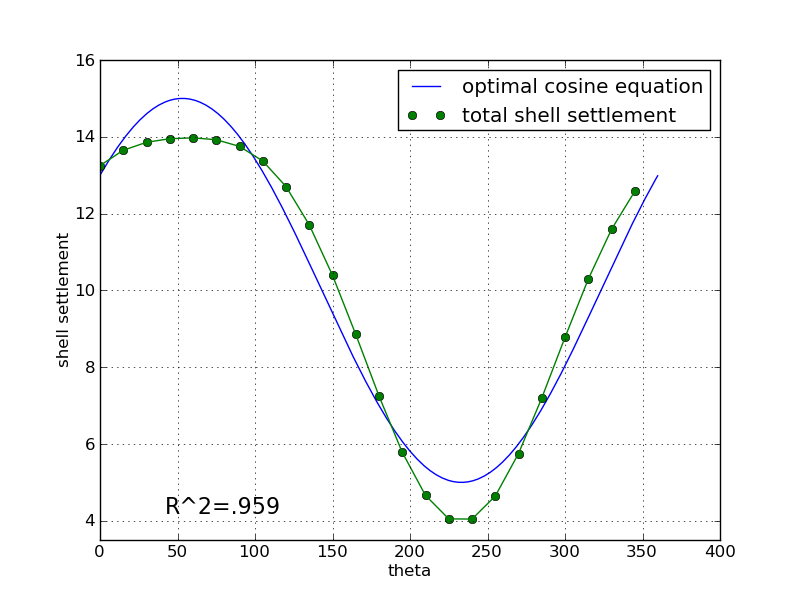
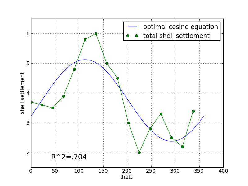
R2 represents what percentage of total shell settlement is accounted for by uniform shell settlement and planar tilt.
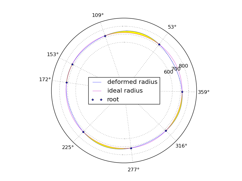
Areas of vapor escape are highlighted in yellow.