1 Overview
1.1 TANK Module
The TANK module can be used to design or evaluate in-service aboveground storage considering sustained and occasional loading in accordance with API 650, API 620, and API 653. The tank shell courses, roof, and bottom components are included in the evaluation. The analysis procedures and references currently implemented in TANK are shown in Table 1. Per API 579-1/ASME FFS-1, the TANK module may be used in conjunction with the APIFFS module to perform fitness-for-service evaluations. Settlement evaluations in accordance with API 653 can be performed using the TANKSETT module. See the respective APIFFS and TANKSETT user manuals for a full description of capabilities.
1.2 Construction Code Rules and Material Property Dates
Code calculations are validated through the following dates/publications.
- API 650 – API Standard 650, Welded Tanks for Oil Storage, Eleventh Edition, 2011 Addendum.
- API 620 – API Standard 620, Design and Construction of Large, Welded, Low-Pressure Storage Tanks, Eleventh Edition, 2012 Addendum.
- API 653 – API Standard 653, Tank Inspection, Repair, Alteration, and Reconstruction, Fourth Edition, 2012 Addendum.
- ASCE 7 – ASCE Standard ASCE/SEI 7-10, Minimum Design Loads for Buildings and Other Structures.
Material properties including physical properties, strength parameters, allowable stress, and toughness curves are available as follows.
- API 650 – API Standard 650, Welded Tanks for Oil Storage, Eleventh Edition, 2011 Addendum.
- API 620 – API Standard 620, Design and Construction of Large, Welded, Low-Pressure Storage Tanks, Eleventh Edition, 2012 Addendum.
- API 653 – API Standard 653, Tank Inspection, Repair, Alteration, and Reconstruction, Fourth Edition, 2012 Addendum.
2 Specifying the Geometry
2.1 Tank Courses
A tank analyzed using the TANK module is assumed to be welded and can have shell course sections of differing heights and thickness. Two methods are available in API 650 for determining required shell thickness, the 1-Foot Method and the Variable-Design-Point Method. API 650 limits the design method used to size the shell course based on the tank’s geometry. Tanks with a diameter greater than 200 feet cannot be evaluated with the 1-Foot Method. The Variable-Design-Point Method may be used for any diameter tank as long as the following limit given in 5.6.4.1 of API 650 is valid.
(1)
2.2 Roof Considerations
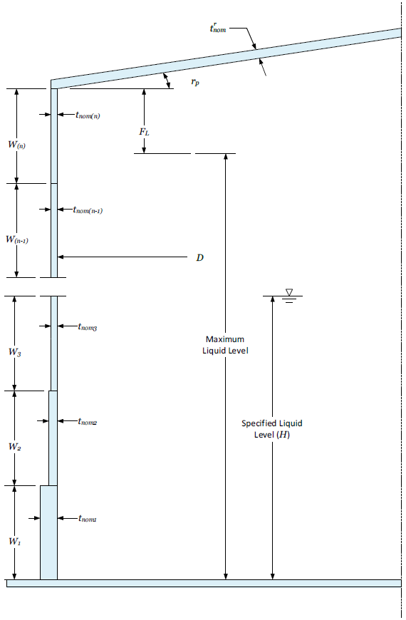
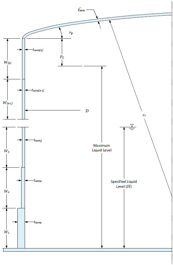
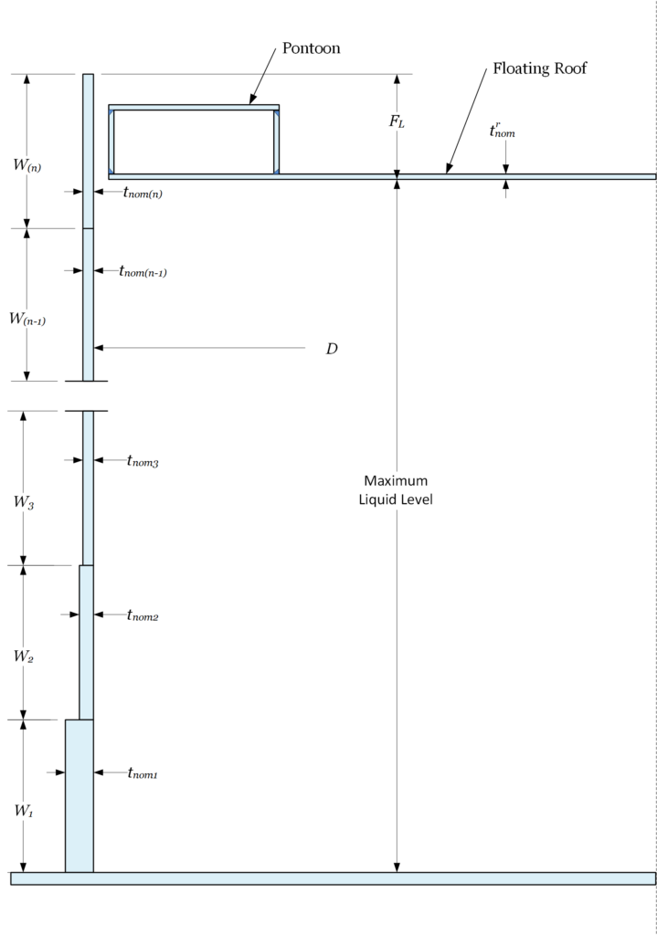
A cone, dome, or floating roof may be specified for the tank (see Figures 1, 2, and 3, respectively). For a self-supported roof, a cone is limited to a slope between 2:12 (9.5 degrees) and 9:12 (37 degrees) while a dome roof must have a minimum radius between 80% and 120% of the tank diameter. The maximum allowable roof plate thickness is 0.5 inches.
2.3 Bottom Considerations
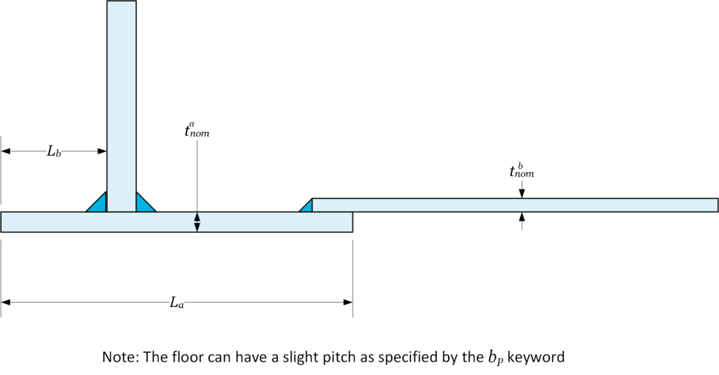
The tank bottom can consist of single-thickness flat plates or single-thickness flat plates with a thickened annular ring (see Figures 4 and 5). Geometric limits relating to thickness for the bottom and annular plate region of the bottom are implemented per part 5.4 and 5.5 of API 650 or paragraphs 4.4.5 or 4.6 of API 653. Appendix I of API 650 governs storage tanks that are supported by grillage. Evaluation of grillage can be activated with the DGRILL keyword. The maximum allowable spacing between grillage members is calculated in accordance with Annex I of API 650 as well as the bottom plate deflection and maximum allowable deflection. The required bottom thickness is determined from the yield and deflection criteria as well as the maximum fill height of the tank based on the specified grillage spacing output.
3 Specifying the Materials of Construction
A specification for the material of construction may be input. From the specification, the following are determined based on the construction code.
- Physical properties including Young’s modulus, expansion coefficient
- Allowable stress
- Minimum specified yield stress
- Ultimate tensile strength
- Toughness curve designation
- External pressure chart
The physical properties may be manually overwritten with user-defined values. The other material properties may also be manually input if a material specification is not available. If both a material specification and user-defined properties are input, the user-defined properties will supersede the properties determined by the material specification using the SAGE Material Database.
The allowable stress is scalable by an input multiplication factor (SAFACT), which can be used to increase or decrease the desired design margin.
4 Specifying the Applied Loads
4.1 Maximum Temperature
The maximum temperature at which an API 650 or API 653 tank can operate is 500°F (260°C) for carbon steel and stainless steel tanks. Tank operations between 200°F (93°C) and 500°F (260°C) are outlined in Appendix M of API 650. For an API 620 tank, the maximum design temperature is 200°F (121°C).
4.2 Internal Pressure
The maximum pressure for an API 650 or API 653 governed tank is 2.5 psi (18 kPa) as given in Appendix M of API 650. The maximum pressure for an API 620 tank is 15.0 psi (103 kPa). The specified internal pressure is only included in the tank shell course calculations for API 620 tanks. Tanks with floating roofs cannot contain internal pressure, and floating roofs are not valid for API 620 tanks. Internal pressure is only applicable to tanks with cone- or dome-shaped roofs.
4.3 External Pressure
The maximum external pressure for an API 650 or API 653 tank is 1.0 psi (6.9 kPa). External pressure need not be considered if the pressure is below 0.036 psi (0.25 kPa). The maximum external pressure for API 620 tanks is limited to 0.0625 psi (0.43 kPa). External pressure calculations are only applicable to tanks with cone- or dome-shaped tank roofs.
4.4 Sustained Loads
The sustained loading consists of the tank structural weight and pressure due to a liquid column, or the combination loading of the pressure due to a liquid column plus any additional internal or external pressure. For the maximum fill height calculation option, the liquid height input is not required. For all other cases, the required inputs are the liquid height, the specific gravity of the fluid contained inside the tank, and any additional internal pressure. If the hydrostatic test option is specified, the fluid specific gravity is assumed to be 1.0. The weights of the shell courses, the bottom, and the roof in the tank are calculated in the corroded and non-corroded states based on the tank diameter and plate thickness for inclusion in the evaluation of occasional loading. The roof weight and bottom plate weight are increased by a factor to compensate for overlap. This factor is calculated assuming a 4×8-foot sheet using the input overlap and is shown below.
(2)
Additionally, the weight of any girders or framing inside the tank must be specified by means of the RFWT keyword. If the roof is partially supported by columns, the percentage of the roof weight supported by these columns must be input. A roof live load can also be specified to account for snow loads or any other top of roof loading. Finally, a weight factor can be included in the weight calculations to account for any additional weight. The weight factor is applied to the material density for all bottom, course, or roof plate weight calculations.
4.5 Occasional Loads
Wind loading may be considered and requires the input of the wind speed. Earthquake loading may be considered and requires the input of the site class, seismic use group, and the spectral response of the ground. These parameters are defined in chapter 11 of ASCE 7.
5 Assessment Method
5.1 General Assessment Techniques
There are two evaluation methods for tank shell courses available in the TANK module. The individual course evaluation method is available for all tank Codes. This is the API 620 course thickness calculation or the 1-Foot Method for API 650 and API 653 tanks (see Table 1). There is also an iterative course evaluation technique available for API 650 and API 653 tanks, referred to as the Variable-Design-Point Method (see Table 1). The 1-Foot Method is always performed regardless of tank size or governing Code. For API 650 and API 653 tanks, the Variable-Design-Point Method may be activated for any size tank but is always activated for tanks greater than 200 feet in addition to the individual course calculations.
5.2 Fluid and Internal Pressure Criteria
For all tanks, requirements for the tank courses are governed by the specified liquid and fill height. The liquid pressure is evaluated using the techniques described in Paragraph 4.1 for the tank courses. For API 650 and API 653 tanks, the internal pressure with respect to the tank roof is evaluated per Appendix F of API 650, and calculations are performed for the following conditions. A failure pressure for the roof is calculated, and the final maximum pressure is limited to 80% of this value. The maximum design pressure is also limited by a criteria to restrict uplift. The last case is based on yielding criteria for the area around the ring of the tank roof. For API 620 tanks, the roof is evaluated using the same criteria as the tank shell courses based on the design pressure.
5.3 External Pressure Criteria
The tank roof assessment technique for API 650 and API 653 tanks subject to external or wind pressure is based on Appendix V of API 650. This assessment technique can be used to determine the thickness or stiffener area required for the tank shell courses and roof. Similarly, if external pressure or a combination loading case of wind plus external pressure is present, the procedure can be used to calculate the required thickness or stiffener area for external pressure. For API 620 tanks, the tank courses and roof are evaluated using the same criteria as described in Paragraph 45.1.
5.4 Stress Calculation (CALC=Z)
The design condition stress evaluation is only applicable to the tank shell courses. The circumferential stress is calculated based on the liquid height above the bottom of each tank course and any specified internal or external pressure. The longitudinal stress is calculated for each course based on the axial force caused by metal weight and roof loads. A summary of the calculated stress based on the design loading is output for each tank course.
5.5 Design Required Thickness (CALC=T)
The required thicknesses for the courses are calculated per the methods described in Paragraph 45.1 and include the specified future corrosion allowance. In addition to the required thickness calculated above, a structural minimum thickness is given per the design standard and compared to the thickness in the corroded state. The minimum thickness varies depending upon which design basis is selected. For API 653, the structural minimum thickness is 0.1 inches, and for API 650 and API 620 tanks, the structural minimum thickness can be found in Table 5.6.1.1 of API 650. The required thickness based on load and structural minimum thickness is output for each course, and a summary table showing the required thickness for all courses is also provided. For API 650 and API 653 tanks, the required thicknesses for dome and cone roofs are calculated per the procedure given in 5.10.5 and 5.10.6 of API 650. Calculations are performed for both the balanced and unbalanced conditions. A detailed assessment of the required structural roof support members for an API 650 tank is not available in the TANK module. If external pressure is specified, the additional calculations given in Appendix V.7 are performed. If the required thickness is calculated to be greater than 0.5 inches, support columns are required, and a message is output. For API 620 tanks, the roof required thickness is evaluated with the same procedure used for the tank course with the applicable loading. A detailed assessment of the required structural roof support members for an API 620 tank is not available in the TANK module. The TANK module will determine if an annular plate is required per the requirements given in part 5.5 of API 650 as well for the wind and earthquake loading conditions as described below. If it is determined that an annular plate is required, but none is specified, a message is printed. If an annular plate is specified, the suitability of the annular plate will be considered for the liquid, wind, and earthquake loading requirements. Additionally, the required thickness of the bottom plate is determined. The structural minimum thickness is 0.361 inches for API 650, 0.25 inches for API 620, and 0.1 inches for API 653.
5.6 Retirement Thickness (CALC=F)
Since storage tanks have extremely large diameter with respect to wall thickness, small changes in diameter due to corrosion will have no significant impact on the component required thickness. Because of this, the retirement thickness for the tank courses, roof, bottom, and annular plate is equal to the calculated tank required thickness less the specified future corrosion allowance and limited by the component structural minimum thickness. Retirement thickness results are output in a similar manner to the required thickness results.
5.7 Maximum Fill Height and Maximum Allowable Working Pressure (CALC=P)
The maximum fill height (MFH) is the maximum liquid level allowed for the storage tank. The MFH is based on the nominal (mean) tank diameter for API 650 and API 653 tanks, the inside tank diameter for API 620 tanks, the course plate thickness, and the material allowable stress. For API 620 tanks, any internal pressure is also considered in the MFH calculations. For each tank course, the maximum allowable liquid pressure is output as well as a summary table for all tank courses that shows the MFH based on the appropriate design code method. The maximum allowable working pressure (MAWP) is only calculated for the tank roof (it is assumed that the tank courses are governed by the MFH). The MAWP is calculated based on the procedures described for internal pressure and external pressure.
5.8 Minimum Design Metal Temperature (CALC=M)
The minimum design metal temperature is evaluated for the tank courses, bottom plates, and annular plate, if applicable. The minimum temperature is calculated based on the toughness curve for the material and the plate thickness for API 650 and API 653 tanks. For API 620 tanks, the minimum temperature is based on the material specification and plate thickness. Special requirements for API 620 Appendix Q and R tanks are not considered. A summary table of the minimum temperatures is provided for all applicable components.
6 Supplemental Assessment Methods
6.1 Tank Roof Junction Requirements
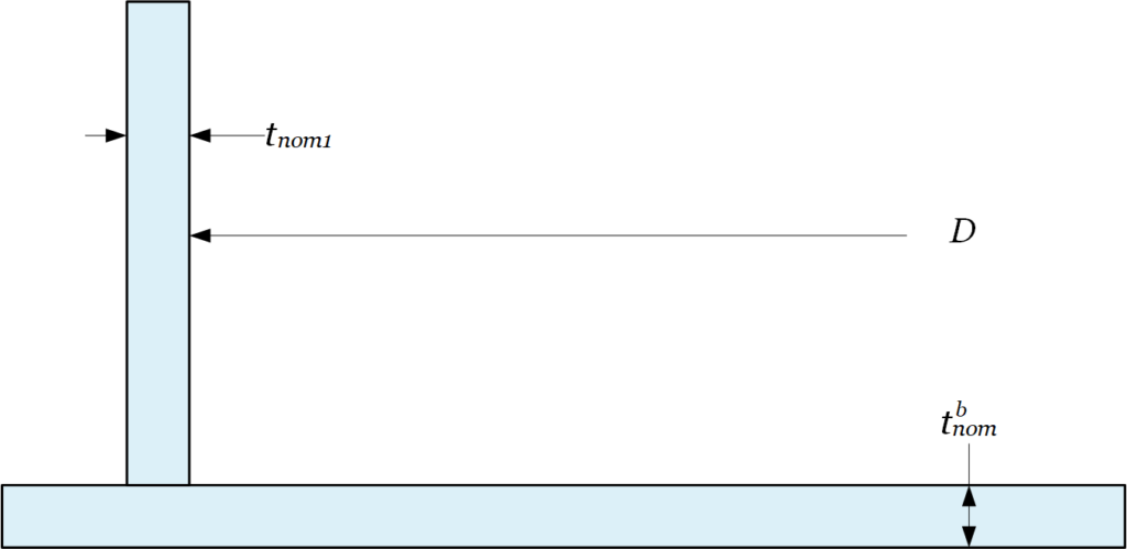
For tanks with cone- or dome-shaped roofs, the top course-to-roof junction compression ring area requirements are evaluated. By default, no additional stiffening members are assumed for the compression ring area region; however, the standard compression ring reinforcement figures from API 650 are available as shown in Figures 6 through 15. Once the corner joint geometry is specified, the required and calculated reinforcement areas are output for the design conditions. In addition, the MAWP limited by the compression area requirements is also provided.
6.2 Wind Suitability Calculations
The TANK module can evaluate wind loading (overturning stability) per Paragraph 5.11 of API 650 by setting the OCCL keyword to WIND or ALL. The forces and moments on the tank due to the wind loading are calculated. In addition, the uplift moments due to wind, internal pressure, and tank weight are calculated and compared to allowable values to determine if mechanical tank anchorage is required. Two load cases are considered: the tank in the full liquid condition and the tank in the empty condition. If a cone or dome roof is specified, the effect of wind pressure is included in a wind modified maximum internal or external pressure for the tank roof based on API 650 Appendices F and V. The pressure calculation is not performed for API 620 tanks.
6.3 Earthquake Suitability Calculations
The TANK module can evaluate the effects of earthquake loading on a tank based on Appendix E of API 650, which is a simplification of the ASCE 7 design code. Earthquake loading can be activated by setting the OCCL keyword to QUAKE or ALL. Earthquake accelerations and site parameters should be specified based on the tank’s geographic location and the seismic information in ASCE 7. Based on the specified earthquake loading and site factors, the impulsive and convective accelerations are calculated. The impulsive and convective response is then used to calculate the maximum hoop stress in the shell courses, which are then compared to allowable values. The longitudinal and shear stresses are also evaluated at the tank bottom junction. The tank overturning moment due to the acceleration is calculated to determine if mechanical anchorage is required. Finally, a minimum freeboard is calculated for the earthquake condition to prevent sloshing, and an error is printed if the specified freeboard is less than the required height.
6.4 Elevated Temperature Thermal Fatigue
An elevated temperature analysis is performed for API 650 carbon steel tanks when the temperature is greater than 200°F and stainless steel tanks when the temperature is greater than 100°F. The analysis consists of a thermal fatigue evaluation of the bottom corner joint. The allowable number of cycles is calculated for the bottom corner joint assuming the tank is completely filled and emptied with each cycle. This analysis is not performed for API 620 tanks.
6.5 Anchor Bolt Suitability
An evaluation of tank anchor bolts can be activated by setting the ANCHOR keyword to MECHCAL. Setting the keyword to MECH only includes the effect of anchorage in earthquake and wind calculations but does not evaluate the bolts themselves. For the MECHCAL option, the bolt geometry, configuration, and material must be specified. If no bolting is specified and occasional loads are present, the need for mechanical anchorage is evaluated based on earthquake or wind loads. If anchorage is required, a warning message will be displayed. If bolting is specified, the tank bolt stress is calculated and compared to an allowable value for the load cases as shown in Table 5-21 of API 650 (see Table 2).
6.6 Wind Girders Requirements
The TANK module is able to evaluate the suitability of specified stiffening rings for the case where wind occasional loads or the combination of wind and external pressure is specified. The unsupported length, defined as the unsupported distance between stiffeners, can be specified for each tank course. The maximum allowable unsupported length is then calculated per section 5.9.7 of API 650 and output. If the unsupported length of any tank course is found to be greater than this calculated value, a warning message is displayed.
7 Nomenclature
D = Tank diameter in feet.T = Tank diameter in feet.
H = Tank diameter in feet.
OLAP = Tank diameter in feet.
8 Tables
Table 1 – References for Tank Calculations Currently Implemented
| Calculation Type | Code | References |
| Tank Shell Course Thickness | API 620 | 5.10 |
| Tank Shell Course Thickness (1 Foot) | API 650 | 5.6.3 |
| Tank Shell Course Thickness (Variable Point) | API 650 | 5.6.4 |
| External Pressure and Wind Loading | API 650 | V.8 |
| Bottom/Annular Plate | API 650 | 5.4 & 5.5 |
| Wind Loading | API 650 | 5.11 |
| Earthquake Loading | API 650 | Appendix E |
| Annular Bottom Plate Thickness | API 650 | 5.5.3 |
| Tank Shell Course Thickness (1 Foot) | API 653 | 4.3.3 |
| Bottom/Annular Plate | API 653 | 4.4.5 & 4.4.6 |
Table 2 – Bolting Summary Table
| Loading Case | Description |
| Design Pressure | Uplift due to internal pressure alone. |
| Test Pressure | Uplift due to internal pressure during a hydrotest. |
| Failure Pressure | Uplift due to internal pressure during roof failure. |
| Frangibility Pressure | Uplift due to internal pressure during failure of the frangible joint. |
| Wind Load | Uplift due to wind loading. |
| Seismic Load | Uplift due to seismic loading. |
| Design Pressure + Wind | Uplift due to internal pressure and wind loading. |
| Design Pressure + Seismic | Uplift due to internal pressure and seismic loading. |
9 Figures