Introduction
Fillet-welded patch repairs are a common and practical solution for pressure vessels and piping that have experienced local wall thinning due to corrosion, erosion, or other damage mechanisms in the oil and gas and petrochemical industries. ASME PCC-2 Article 212, Fillet Welded Patches, is the most referenced industry guidance for the design of fillet-welded patch repairs. However, the current Article 212 guidance is known to be conservative and frequently results in unnecessarily thick patch plates — in many applications exceeding 1.5 inches. This threshold is significant because it mandates post-weld heat treatment (PWHT) for carbon steel repairs, which adds cost, schedule, and operational complexity. Avoiding unnecessary PWHT is therefore a meaningful practical objective for plant integrity and reliability engineers.
Equity Engineering has been actively developing a simplified, less conservative, and technically rigorous alternative to the current ASME PCC-2 guidance. Originally presented at the ASME 2024 Pressure Vessels and Piping (PVP) Conference [1], this work has since been refined and extended. This article summarizes Equity’s updated proposed guidance, highlights what is new since the 2024 paper, and provides context on ongoing collaborative efforts with other organizations at the ASME PCC-2 Subgroup level to incorporate improved fillet-welded patch design guidance into the standard.
Limitations of Current ASME PCC-2 Guidance
For fillet-welded patches, ASME PCC-2 Article 212 provides two design equations, Equations (4) and (5) (Figure 1), summarized in Table 1.
Table 1: ASME PCC-2 Article 212 Design Equation Characteristics
| Characteristic | Equation (4) | Equation (5) |
| Governs | Global pressure stresses | Local bending from eccentricity (thickness offset) |
| Weld size included? | Yes | No — stress depends only on patch thickness, shell thickness, and mean diameter |
| Back bevel credit | None | None |
| Amplification factor | 1.82x through joint efficiency consideration | 1.67 to 7.0× nominal hoop stress, depending on T/t ratio |
| Resulting thickness requirement | T ≥ 1.82 × required shell thickness | T ≥ 3.28 × required shell thickness |
| Frequently governs? | No | Yes |

Equation (5) frequently governs, though a notable limitation that although it is presented as a weld stress calculation, weld size does not appear in the equation — the calculated stress depends only on the patch plate thickness, shell thickness, and mean diameter.
Analysis of Equation (5) shows that it applies an amplification factor of 1.67 to 7.0 times the nominal hoop stress to account for eccentricity-induced bending, depending on the patch-to-shell thickness ratio (T/t), and suggests that the patch thickness needs to be at least 3.28 times the required thickness of the shell. When the shell required thickness is close to its nominal thickness, the required patch thickness frequently exceeds 1.5 inches, thus triggering mandatory PWHT.
The key finding from Equity Engineering’s parametric finite element study is that the bending stresses induced by eccentricity are secondary in nature — not primary — and do not adversely affect the plastic collapse load of the repaired component. This finding undermines the technical basis for the large thickness penalties prescribed by Equation (5).
The T-min Approach — Equity’s Updated Proposed Guidance
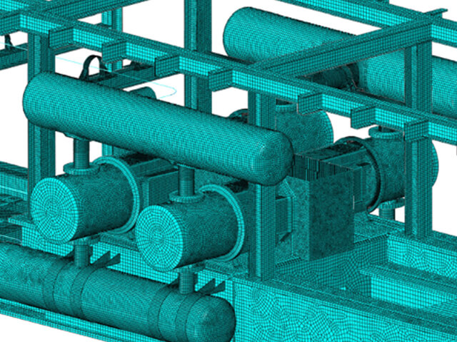
Referred to as the T-min approach, Equity’s proposed methodology is based on a parametric study using elastic-plastic finite element analysis (FEA) in accordance with ASME Section VIII Division 2 Part 5 Design-by-Analysis methodology. Over 1,620 FEA cases were evaluated (Figure 2), spanning R/t ratios of 10 to 100, patch-to-shell thickness ratios (T/t) of 1.0 to 3.0, patch half-angles of 5° to 90°, and both 1:1 and 2:1 fillet weld configurations. For details on the analysis methodology and the results, refer to the PVP2024 paper [1].

The simulation results from the PVP2024 paper are summarized in Figure 3, where the maximum allowable working pressure (MAWP) estimated from FEA collapse loads is compared against the MAWP calculated following the same logic as Equation (4) of Article 212, with three modifications:
- Minimum weld leg dimension is replaced with the minimum of the shell thickness, patch plate thickness, and effective weld throat thickness
- Joint efficiency factor is taken as 1.0
- Resulting force is divided by the mean diameter to convert to pressure
The calculated MAWP is given by:
Equation 1
Where,
t = nominal thickness of the shell
T = nominal thickness of the patch plate
th = throat thickness of the fillet weld between the shell and patch plate
Dm = mean diameter
D = inner diameter of the shell
Sα = allowable base metal stress at design temperature

Figure 3 shows excellent agreement between the calculated and FEA-estimated MAWP: 1,609 out of 1,620 data points fall on or above the 1:1 line, and the 11 data points below the line have a minimum value of 99.37% of the calculated MAWP — essentially on the line. This demonstrates that a joint efficiency of 0.55 as prescribed in Equation (4) is not required for strength considerations. Furthermore, the results confirm that local bending stresses due to eccentricity are secondary in nature, and no separate consideration such as that prescribed by Equation (5) is required. The modified Equation (4), as presented above, adequately captures the load-bearing capacity of the patch plate-to-shell junction.
It should be noted that the FEA parametric study did not explicitly model back-bevel geometry or gaps between the patch plate and shell. These aspects are being investigated by other committee members. The extension of the procedure to account for back-bevel geometry and plate gaps is based on engineering judgment that the additional simulations, when performed, will follow the same trend. Additionally, only internal pressure was considered in the simulations.
Table 2 summarizes the key differences between the current Article 212 approach and the T-min methodology.
Table 2: Current ASME PCC-2 Article 212 vs. Equity T-min Approach
| Characteristic | Current ASME PCC-2 Article 212 | Equity T-min Approach |
| Governing equations | Equations (4) and (5) both required | Simplified procedure developed based on modified Equation (4) only |
| Joint efficiency | 0.55 | 1.0 (with MT/PT inspection) |
| Eccentricity bending treatment | Separate amplification via Equation (5) required | Not required — bending stresses are secondary |
| Back bevel credit | None | Explicit closed-form equations provided |
| Typical patch plate thickness | Frequently exceeds 1.5 inches | Less conservative; often avoids 1.5-inch threshold |
| PWHT risk | Frequently triggered | Reduced |
| FEA-validated | No | Yes — over 1,620 cases per ASME Section VIII Div. 2 Part 5 |
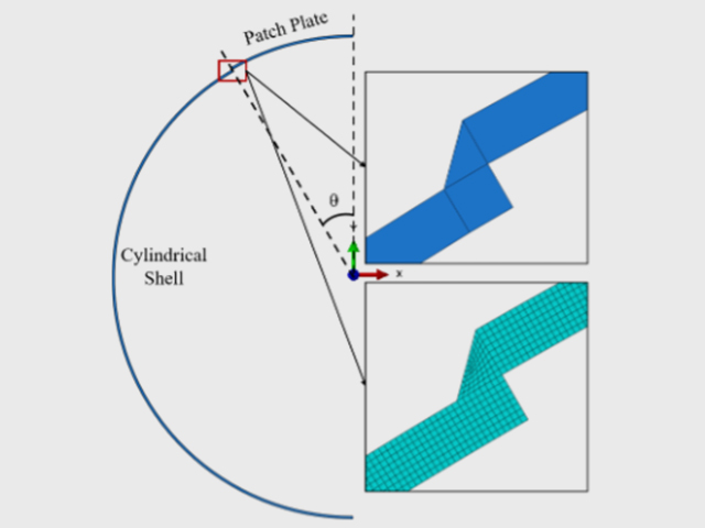
The updated step-by-step guidance is as follows (see Figure 4 for an illustration of a shell-to-patch plate junction). The proposed guidance is intended to replace Equations (4) and (5) of ASME PCC-2 Article 212 for the determination of patch plate thickness and weld sizing. All other requirements of Article 212 remain applicable and shall be followed in conjunction with this guidance.

- STEP 1: Determine minimum required thickness of the patch plate, tpatchmin, for pressure load and any other applicable loads.
- Use joint efficiency of 1.0 in the calculations if MT or PT inspection (or equivalent) can be performed on the weld preparation and on every weld pass through completion of the weld.
- If MT/PT or equivalent inspection is not feasible, the designer may select an appropriate joint efficiency based on engineering judgment, considering factors such as weld joint geometry and welding conditions.
- STEP 2: Determine required nominal thickness of the patch plate as follows:
- STEP 3: For the chosen weld details, verify that the effective weld throat thickness . If not satisfied, increase the weld leg dimensions. Increase in STEP 2, if required, to accommodate larger weld legs.
Equation 2
Equation 3
Equation 4
If the separation at the faying edge of the patch plate is 1.5 mm (1/16 inches) or greater, the gap shall be deducted from the α1, b1, and b2 dimensions.
Note: The procedure outlined above represents Equity’s proposed guidance. Neither this method nor an equivalent has been approved by the ASME PCC-2 Subgroup on Welded Repairs at this time. Engineers intending to apply this procedure should exercise appropriate engineering judgment prior to use.
Derivation for the Effective Weld Throat Thickness Equations – General and Simplified Cases
A derivation of explicit equations for the effective weld throat thickness of a fillet weld with a back bevel is shown below. General as well as special cases are presented herein.

The weld cross-section forms a triangle with the joint root as the apex (point A) and the diagrammatic weld face as the base. The geometry is defined by three parameters: α1 (vertical leg of the main fillet weld), b1 (horizontal leg of the main fillet weld), and b2 (horizontal run of the back bevel). The effective throat, th, is the shortest perpendicular distance from the root to the diagrammatic weld face. Two cases arise depending on the geometry:
Case 1 – ∠DAC ≤ 90º (acute angle), see Figure 1(a)
Condition for ∠DAC to be an acute angle:
Case 2 – ∠DAC > 90º (obtuse angle), see Figure 5(b).
Condition for ∠DAC to be an obtuse angle:
The perpendicular line from D to side AC falls outside of the ΔACD. Therefore, the shortest distance becomes the side AD itself.
Gap Between Plates, Figure 5(c):
When the gap exists between the plates, effective throat should be calculated from Figure 5(c)). All three dimensions, α1, b1 and b2, should be adjusted in the effective throat calculations as follows.
Where,
α = fillet weld angle
θ = back bevel angle
Special Cases – no back bevel
Equal leg fillet weld, substituting α1 = b1 in Equation (5),
Special Cases – equal leg fillet weld with back bevel and b2 ≤ b1
If b2 ≤ b1 only Case 1 is applicable
Substituting α1 = b1 in Equation (3),
When there is a gap between the plates and ignoring the angle effects on gaps (should be reasonable for small gaps less than 3/16 inches) the following equation applies.
The equations address the practical case where a gap exists between the patch plate and the shell at the faying edge. For small gaps (less than 3/16 inches), a simplified gap correction can be applied directly to the weld leg dimensions without accounting for bevel angle effects.
Summary
The current ASME PCC-2 Article 212 guidance imposes thickness penalties that frequently trigger unnecessary PWHT. Equity Engineering’s parametric FEA study demonstrates that the bending stresses driving those penalties are secondary in nature and do not govern plastic collapse, forming the basis for a simpler, less conservative design procedure that more often avoids the 1.5-inch PWHT threshold. Equity continues to participate in the ASME PCC-2 Subgroup on Welded Repairs as this work in collaboration with other industry contributors’ advances toward incorporation in the 2030 edition of the standard and routinely applies this methodology to support clients navigating fillet-welded patch repair decisions in the field.
References
[1] Kummari, S.R., Macejko, B., Bifano, M.F.P., and Jones, J.R., “Proposed New Guidance for the Design of Fillet Welded Patches,” PVP2024-123337, Proceedings of the ASME 2024 Pressure Vessels and Piping Conference, July 29 – August 2, 2024, Bellevue, Washington, USA.
[2] ASME PCC-2-2022, Repair of Pressure Equipment and Piping, Article 212.