Because aboveground storage tanks are large and flexible in nature, these structures are prone to out-of-roundness and shell distortions that may impact a tank’s mechanical integrity. This article will discuss the sources of tank shell distortions, associated risks, evaluation techniques, and options for remediation.
Sources of Shell Distortions
One common source of in-service shell distortions is out-of-plane settlement of the tank bottom edge. The cylindrical shell must satisfy this non-planar boundary condition. Considering in-plane stretching and shear of the shell are orders of magnitude higher than out-of-plane bending, the shell satisfies this boundary condition through radial deformation because it is the lowest energy route. The result is ovalization or out-of-roundness of the shell.
Other sources of shell distortion include fabrication tolerances, buckling due to vacuum, mechanical impact (such as equipment impacting the tank shell resulting in a dent), and wind/seismic loading.
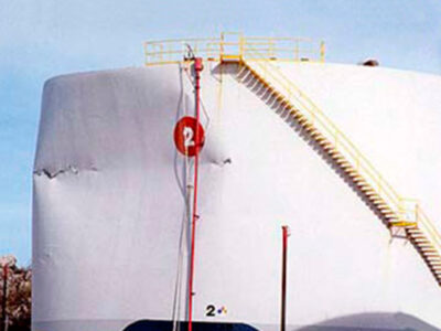
Wind loading creates differential pressure on the tank wall, which can cause the shell to buckle due to its inherent flexibility. Tanks are less susceptible to wind-induced buckling in the filled condition since the hydrostatic pressure inside the tank helps resist the external pressure caused by wind. Due to this interaction, wind-induced buckling tends to favor the upper shell courses of the tank where there is less hydrostatic pressure. Figure 1 shows an example of wind-induced buckling in a storage tank.


Seismic loading can also result in shell distortions. Contrasting from wind loading, storage tanks are more susceptible to seismic-induced distortions in the full fill condition. During a seismic event, the fluid mass within a tank responds in a combination of impulsive (bulk lateral motion of the fluid) and convective (sloshing) modes. As the mass of the fluid shifts to one side of the tank, a large bending moment is exerted onto the shell wall which can overload the tank, especially at the shell-to-floor junction. The shell simultaneously carries a large hydrostatic pressure load and axial compressive load. The shell can buckle in this biaxial stress state, leading to a circumferential bulge (often referred to as an “elephant’s foot” due to its appearance) appearing along a portion of the tank. Figure 2 shows an example of seismic-induced buckling in a storage tank.
More on Tank Settlement
Annex B of API 653 covers the evaluation of tank settlement. The primary modes of settlement associated with shell distortions are:
- Differential shell settlement – deviations from a uniform vertical settlement or planar tilt which induce stresses in the shell.
- Edge settlement – typically a vertical “drop off” of the floor in the radial direction moving towards the shell-to-bottom corner often associated with foundation issues.
One, both, or neither of these forms of settlement have been observed with and without shell out-of-roundness; it is difficult to predict how a flexible tank structure will respond to the stresses induced by these actions. Similarly, damage to support structures for fixed roof tanks can also interact with settlement and/or shell distortions as these flexible systems interact.
Annex B documents a procedure to evaluate differential settlement of a tank shell. The procedure begins with fitting an optimum cosine function to the settlement inspection points. The cosine function takes the general form:
Where,
- Elevpred = predicted elevation by cosine function
- θ = angular location around tank circumference
The coefficients a, b, and c are numerically solved for to produce the greatest coefficient of determination (R2). The optimum cosine fit is only considered valid if the R2 is greater than or equal to 0.9. Figure 3 (Figure B.3 of API 653) demonstrates a cosine fit to tank settlement.
If a valid cosine fit can be achieved, a maximum permissible out-of-plane settlement value can be calculated as follows:
Where,
- Smax = maximum out-of-plane deflection (ft)
- L = arc length between measurement points (ft)
- Y = yield strength of shell material (psi)
- E = Young’s modulus (psi)
- H = tank height (ft)

If the magnitude of out-of-plane settlement is less than the permissible limit at all locations, the settlement is considered acceptable per this method.
For cases where a valid optimum cosine fit cannot be achieved or the tank fails the optimal cosine acceptance criteria, the arc length method can be used per Annex B. This procedure involves determining the settlement arc length (Sarc) from the settlement inspection data. Annex B provides illustrations and a general procedure for determining Sarc values; however, the procedure is iterative, and numerical methods are often used.
Similar to the cosine method, the arc length method requires a maximum permissible out-of-plane deflection to be calculated:
- Smax = maximum out-of-plane deflection (in)
- Sarc = effective settlement arc (ft)
- Y = yield strength of shell material (psi)
- E = Young’s modulus (psi)
- D = tank diameter (ft)
- H = tank height (ft)
If the magnitude of out-of-plane settlement is less than the permissible limit at all locations, the settlement is considered acceptable per the method.
If the methods of Annex B cannot qualify the out-of-plane deflection, Annex B permits the use of more rigorous evaluation. For these cases, a Level 3 assessment in accordance with Part 8 of API 579-1/ASME FFS-1, Fitness-For-Service (API 579) is typically employed.
Evaluation of Tank Shell Distortion
Although API 653 provides a detailed evaluation procedure for tank settlement, shell distortions still need to be qualified. API 653 provides radius tolerances as a function of tank diameter in Table 10.2 (shown in Figure 4).
If the observed out-of-roundness is within the limits of Table 10.2, the distortion is considered acceptable. Otherwise, a more rigorous assessment may be required such as a Level 3 assessment per Part 8 of API 579.

The Level 3 procedure involves modeling the tank shell using finite element analysis (FEA), with explicit mapping of the distortion data onto the model. Applicable loading of the distorted structure is then simulated and checked against the relevant failure modes (plastic collapse, local failure, buckling, ratcheting, etc.) in accordance with Annex 2D of API 579.
It is important to note that the Level 1 and 2 procedures of Part 8 are limited in applicability. Specifically, the Level 1 and 2 procedures are only applicable if the component under evaluation is a cylinder with out-of-roundness, and the out-of-roundness is constant along the axis of the cylinder. If local deviations of the cylindrical shell occur in the longitudinal direction, the Level 2 assessment procedure can produce non-conservative results, and the shell distortion should be classified as general shell distortion requiring a Level 3 analysis. Given the nature of tank shell distortions typically produces longitudinal shell deviations, a Level 3 analysis is often warranted.
A critical input into the analysis is the shell distortion data. This data can be obtained through surveys of the tank obtaining plumb and roundness measurements. With the growing use of laser scanning technology, however, distortion data is commonly captured via tank shell scanning (either internally or externally). The data is provided in cloud point data format that must be mapped onto the FEA model.
Although laser scanning can be a cost-effective inspection option, some considerations must be taken to properly condition the data for use in an FFS assessment:
- The data should have well-defined reference points to relate the data to the model geometry.
- Units of measurement should be clearly defined such that scaling can be performed if necessary.
- Obstructions in the data should be removed including piping, shell attachments, scaffolding, personnel, etc.
Once the data is processed, it can be incorporated into the FEA model as shown in Figure 5.

Once the damage is accurately characterized in the model, loads can be simulated to determine damage acceptability. Typical loading applicable to most storage tanks includes weight, hydrostatic pressure, wind, and seismic loading. For directional load such as wind/seismic, it is important to check loading in multiple directions due to asymmetric nature of distortion, i.e., the tank may be more susceptible to failure due to loading in one direction compared to another.
As discussed earlier in this article, hydrostatic pressure resists the external pressure imposed by wind loading. Therefore, it is typically appropriate to assess the tank for wind loading in the empty condition.
Tank distortion FFS assessments are typically focused on the load-carrying capacity of the distorted shell, but it is also important to consider the potential for crack propagation. Visual examination and some sort of surface examination (PT, MT) should be carried out in any distorted regions with sharp transitions, kinks, or other rapid changes in curvature, particularly in areas near welds whose residual stress fields can propagate cracks introduced by the distortion. Pressure-related tank distortion (operating, wind, etc.) will typically feature large, relatively gradual buckling lobes. Mechanical impact or local features (tank shell attachments) can create sharper features that may require a different assessment approach more focused on potential fracture concerns.
If the results of the FFS analysis demonstrate the tank is adequately protected against all relevant failure modes, then the tank is considered fit for service for continued operation.
While the methods discussed herein primarily address integrity concerns, serviceability must also be considered. For example, binding a floating roof may limit the operation of a distorted tank.
Remediation Methods
When shell distortions cannot be qualified using the methods described in this article, repair or replacement of the tank and/or foundation may be required. For tanks where a Level 3 FFS assessment is performed, repair scope may vary depending on the results of the assessment. For example, if the tank shows adequate protection for relevant failure modes under hydrostatic pressure but fails under wind loading, intermediate wind stiffeners may be installed to resist wind loading, which can be verified using the FEA model.
In cases where wind loading limits and immediate repair is not practical, a minimum fill height may be required to resist the wind loading if a minimum required fill height can be demonstrated in the FFS assessment. In cases where the shell distortion is attributed to settlement, the tank may require foundation repairs and/or ground improvements to prevent additional damage. For local shell distortions that have plastically deformed or experienced severe deformations, complete removal and replacement of the effected plates may be required. Repair requirements of Section 9 of API 653 should be met in all cases.
Case Study
Industry: Petrochemicals | Location: US facility
Key outcomes: Tank returned to full-fill service under hydrostatic loading. Wind and seismic buckling failure modes were identified and resolved. Remediation scope was defined without full tank replacement.
Issue: An aboveground storage tank experienced differential shell settlement resulting in shell distortion, with measured out-of-roundness and plumbness exceeding API 653 acceptance criteria. The tank was in non-cyclic service, and future settlement was believed unlikely, but the existing screening methods could not qualify the tank for continued operation.
Solution: Equity Engineering performed a Level 3 FFS assessment in accordance with Part 8 and Annex 2D of API 579. A three-dimensional finite element model was constructed in Abaqus/CAE, including all shell courses, the bottom, top angle, wind girder, and nozzles/manways greater than NPS 10. Laser-scanned point cloud data of the shell distortion was processed and explicitly mapped onto the model, and non-linear elastic-plastic analysis was performed across all applicable load cases, including hydrostatic fill, weight, wind, and seismic loading.
Result: The tank passed both the plastic collapse load case and the equivalent plastic strain check under full hydrostatic fill. However, buckling assessments revealed the tank could not achieve the required load under wind loading in one direction, or under seismic loading in any direction. These findings isolated the governing failure modes to specific load conditions, allowing the client to pursue targeted remediation, such as wind stiffener installation, rather than full tank replacement or unnecessary out-of-service time.
Conclusion
Tank shell distortion assessment bridges inspection, structural analysis, and remediation planning, where timing and technical depth directly impact both equipment life and operational safety. Equity Engineering brings integrated expertise in conducting rigorous API 653 and API 579 evaluations, interpreting complex laser-scan data, and developing remediation roadmaps that balance structural integrity with cost and schedule. Our teams have guided clients through distortion cases ranging from settlement-induced out-of-roundness to seismic-induced buckling, translating FEA results into actionable repair scopes and operational limits. Whether your tank requires Annex B screening, a comprehensive Level 3 assessment, or foundation-to-shell integration planning, the right evaluation approach can prevent costly surprises and extend tank asset life when executed early in your inspection or turnaround planning cycle.