Introduction
An API RP 581 assessment of a refrigerated ammonia storage tank almost always returns the same recommendation: inspect at the earliest opportunity. The consequence of a large anhydrous ammonia release is severe, the tank rarely qualifies as leak-before-break, and the uncertainty associated with ammonia stress corrosion cracking (SCC) drives the probability of failure (POF) upward. The resulting risk exceeds the target almost from the day the tank enters service.
The difficulty is that the inspection prescribed by risk-based inspection (RBI) can itself degrade the condition of the tank. Removing a refrigerated tank from service means it is emptied, warms, and allows air in. Oxygen is one of the primary drivers of ammonia SCC, and recommissioning is a critical window for crack initiation and growth, so an internal inspection that finds no damage can still leave the tank in worse condition than before the inspectors arrived. Owners are caught between a risk model that calls for the inspection and a damage mechanism that makes it counterproductive.
Equity Engineering has developed a multidisciplinary approach that integrates RBI and fitness-for-service (FFS) to better characterize the POF in high-consequence scenarios. This approach has been applied to refrigerated ammonia tanks at fertilizer and chemical sites across the U.S., as well as more recently to vinyl chloride monomer (VCM) storage spheres. This article describes how and where FFS best supports RBI and presents several applications from projects completed by our team.
Refining RBI with FFS
API 581 is strong on consequence because fluid properties, inventory, toxicity, and operating conditions are well defined and used directly in the consequence calculation. The generic assumptions reside in the POF.
The API 581 POF methodology starts with a generic failure frequency (GFF), i.e., an industry-wide leak frequency for the component type, which is then scaled by a damage factor and a management systems factor. For thinning, the damage factor depends on how close the wall is to a minimum thickness determined by code calculation. For environmental cracking, the damage factor is based on a susceptibility ranking. Both damage factors credit the effectiveness of past inspections for the specific damage type, but neither accounts for the stresses in the equipment, its tolerance for flaws, or the manner in which it is operated.
On ordinary equipment, the effect of these simplifications is negligible. On high-consequence equipment, they govern the result, because when consequence is very large, a modest error in POF shifts the inspection date by years. A susceptibility-driven cracking damage factor cannot distinguish a highly stressed weld from a lightly loaded plate. For equipment built with no corrosion allowance, the code minimum thickness is nearly equal to the nameplate thickness, so any measured wall loss appears urgent. API 581 also provides no methodology at all for some components, including tank roofs, nozzles, and internal structure, which still require an inspection basis.
FFS is not cost-justified for every RBI assessment; it is warranted when the equipment design is conservative, the consequence is inherently high, the governing damage mechanism is difficult to model, or removing the equipment from service is lengthy, expensive, or carries risk in its own right. Refrigerated ammonia tanks meet all four criteria.
Download the Risk-Based Inspection (RBI) Consulting Overview
Risk-based inspection (RBI) quantifies risk and gives you the wisdom to make informed decisions about how, where, and when to inspect assets.
Four RBI + FFS Applications
An assessment per API 579-1/ASME FFS-1 can inform an RBI assessment at four points. These applications differ in rigor, and not all of them extend inspection intervals.
1. Alongside API 581’s POF, Not in Place of It
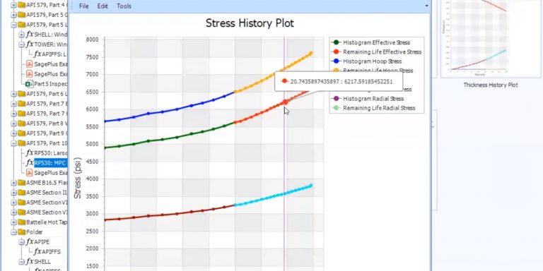
Critical flaw sizing with the failure assessment diagram (API 579 Part 9) defines the combinations of crack depth and length that a location can tolerate. Crack growth calculations (Annex 9F) estimate the time required for a flaw at the limit of NDE detection to reach that envelope. When these calculations are run thousands of times with varied inputs, the crack growth model becomes a Monte Carlo simulation, and the fraction of simulations that have failed by each year form a POF curve. Multiplying this curve by the API 581 consequence of failure (COF) for the location produces a risk curve that can be compared with the risk target.
The two POFs are different quantities. The API 581 POF is a scaled industry frequency that covers every cause of loss of containment. The Monte Carlo POF is the probability that a postulated flaw, at one location and under one mechanism, grows to critical size. Both can be expressed in events per year, but the physics-based Monte Carlo POF is conditional on the flaw existing, whereas the API 581 risk target was set against the GFF-based scale. Comparing one against a target built for the other therefore requires engineering judgment. The Monte Carlo POF result can show when risk begins to climb, where it climbs first, and whether the RBI interval holds up, but it cannot be substituted directly for the API 581 POF.
2. Thickness Inputs
For thinning, the minimum thickness from a Level 2 or Level 3 assessment can replace the code minimum thickness used in the damage factor calculation. This substitution is most valuable for equipment with no corrosion allowance.
3. Hole-Size Distribution
API 581 distributes the GFF across a fixed set of release hole sizes, from small leaks to rupture, regardless of material or damage mechanism. FFS can establish which of these failure modes are physically credible.
If a tank does not satisfy leak-before-break, a crack can reach critical length before a leak is detected, so medium and large holes are not realistic precursors to failure. The frequency typically assigned to medium and large holes belongs with the rupture case, which carries a high consequence. This is the result most commonly seen with ammonia tanks. However, the same logic works in both directions. Equipment that satisfies leak-before-break will leak detectably before it ruptures, so the rupture frequency can shift to smaller holes and the consequence decreases. The damage mechanism also matters: cracking may lead to a near-instantaneous rupture, whereas pitting and localized thinning produce small holes before any rupture. FFS clarifies the type of release, which further refines the consequence calculation.
4. Inspection Scope
The FFS assessment identifies the limiting locations and the smallest flaw size that the applied NDE must be capable of detecting, and both are integrated into the inspection plan. This is often the most valuable output of the entire assessment.
Case Study #1: Refrigerated Ammonia Tanks
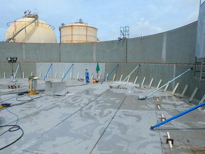
The three tanks in Table 1 were evaluated using the same three methods: a quantitative API 581 assessment; a qualitative assessment per Fertilizers Europe’s guidance for atmospheric refrigerated ammonia tanks; and an FFS assessment consisting of elastic stress analysis, critical flaw sizing, ammonia SCC crack growth, and probabilistic simulation based on the operating fill history of each tank.
| Table 1: Integrated RBI and FFS Results for Three Refrigerated Ammonia Storage Tanks | |||
| U.S. Ammonia Storage Site #1 | U.S. Ammonia Storage Site #2 | U.S. Fertilizer Plant | |
| Tank | 130 ft (39.6 m), single wall, API 620, A537 Cl 1, in service mid-2010s | 115 ft (35.1 m), single wall, API 620 App. L and R / API 625, A516-60N, 2017 | 7,000 ton (6,350.1 tonne), single containment, LT75 and A-201B, about 1960 |
| API 581 | Inspect at earliest availability. POF 1.6E-03/yr; COF about 200,000 ft2 (18,580.6 m2) and $200MM USD; 2-yr interval even with A-level inspection | Inspect at earliest availability. POF 1.6E-03; COF about 240 ft2 (22.3 m2) and $500,000 USD | Inspect at earliest availability. POF 9.9E-02/yr; COF about 6,200 ft2 (576 m2) and $5.5MM USD |
| Fertilizers Europe | Medium risk; 10 to 15 yr | Medium risk; 10 to 15 yr | Medium-high risk; 5 to 10 yr |
| FFS | Risk target reached at 15 yr from a 0.080 × 0.300 in. (2.032 × 7.620 mm) flaw | Limiting location at bottom shell-to-annular plate joint reached risk target at 23 yr from a 0.031 x 0.188 in. (0.7874 × 4.775 mm) flaw | Limiting location at bottom corner joint reached risk target at 14.8 yr from a 0.080 × 0.300 in. (2.032 × 7.620 mm) flaw |
| Recommendation | AE testing, 15-yr initial interval | AE testing, 10-yr initial interval | AE testing, 10-yr initial interval |
API 581 returned the same recommendation for all three tanks: inspect at the earliest availability. For U.S. ammonia storage site #1, API 581 calculated a POF of 1.6E-03 events per year, driven by ammonia SCC, and a consequence of roughly 200,000 ft² (18,580.6 m²) and $200 million USD. Even with A-level inspections, the resulting interval was two years. For a tank in which opening the vessel introduces the damage mechanism, this is not a workable inspection plan.
The Fertilizers Europe method is a qualitative scorecard built on a member survey of 48 tanks. It considers factors API 581 does not, including operating experience, commissioning and decommissioning procedures, secondary containment, and water and oxygen control. It placed two tanks at medium risk with a recommended interval of 10 to 15 years and the third at medium-high risk with a recommended interval of 5 to 10 years.
The FFS assessment addressed a narrower question: how long a near-detectable flaw at the worst location takes to bring risk to the target. The final recommendations did not simply adopt the FFS interval. For U.S. ammonia storage site #1, the Fertilizers Europe and FFS results together supported acoustic emission (AE) testing on a 15-year initial interval. At the U.S. fertilizer plant, the FFS supported an interval of approximately 15 years, but the Fertilizers Europe result governed. The second U.S. site was assigned a 10-year interval with AE testing. Because the three methods answer different questions, reconciling them requires engineering expertise. Calculated crack growth life is not a prediction of time to failure. Ammonia SCC can remain dormant for long periods and then grow quickly when conditions change, so the probabilistic result informs a risk judgment rather than making one.
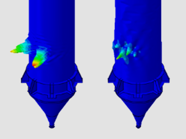
Equally important, the FFS assessment identifies critical locations for inspection. At the second U.S. ammonia storage site, the stress analysis showed the highest flaw sensitivity at the annular plate-to-shell weld, where hydrostatic loading rotates the bottom corner, and at the shell course 1 nozzles and manways, longitudinal seams, and tee intersections. AE sensors were placed at these locations, and each plan required that the detection capability be sufficient for the flaw sizes analyzed. FFS also showed that the floor away from the annular plate carries little applied stress, so it is a low inspection priority provided the foundation heating system is maintained and differential settlement remains small.
Case Study #2: VCM Spheres
Six VCM storage spheres at a southern U.S. chemical plant presented a different problem. The spheres are 80 feet (24.4 m) in diameter and built to ASME Section VIII, Division 2; three are SA516-70N from 1990 and three are SA537 Class 2 from 1996. They were designed with no corrosion allowance and were on 10-year internal inspection intervals, with each internal inspection requiring 18 to 24 months out of service. The owner wanted to extend the internal inspection interval or transition to non-intrusive inspection.
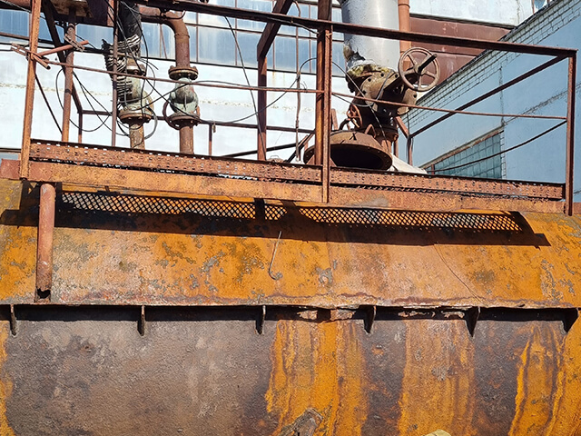
The assessment combined API 581, a proactive Level 3 FFS of the sphere petals and support components per Part 4 and Annex 2D of API 579, and a corrosion under insulation (CUI) susceptibility assessment. The CUI assessment used explainable-AI technology built on probabilistic, physics-based modeling and calibrated to the site’s operating temperature, coating and jacketing, and climate. Two internal inspections had found no thinning concerns, but an external inspection with the insulation stripped revealed widespread mild to moderate CUI. The RBI calculation was run twice: once with the API 581 CUI rates and once with the rates from the CUI susceptibility assessment.
The FFS determined a higher minimum thickness than the RBI calculation, most likely because the RBI calculation considered hoop stress only, whereas the Level 3 assessment included all stresses on the petals and supports. For CUI, the worst-case rate from the susceptibility assessment was about 17% lower than the API 581 rate, and the more probable rate about 28% lower. Both the FFS and the CUI susceptibility assessments were used to reduce some of the conservatism in the RBI assessment.
Other Ways to Combine FFS and RBI
The same logic used to integrate FFS with RBI in the ammonia and sphere work described above can extend further:
- Analytical POF from crack growth and critical flaw size. As discussed previously, an API 581 cracking damage factor infers the POF from a susceptibility ranking and inspection credit. Crack growth models and critical flaw sizes allow the POF to be determined analytically instead. The approach used on the ammonia tanks can be transferred to other forms of cracking, wherever credible crack growth data exist.
- Analytical COF from failure mode. API 581 assigns release frequencies across a generic set of hole sizes. As the ammonia tank case studies demonstrate, the fracture mechanics of the damage mechanism can be utilized to better understand the failure mode. Ammonia SCC produces cracks, and the critical flaw sizing showed that a crack would become unstable before it could open into a medium or large hole, so any release larger than a small leak would become a rupture. Adjusting the GFFs accordingly gave the consequence calculation a hole-size basis grounded in the physics of the equipment rather than a generic split. The same approach applies to vessels and piping in high-consequence service, where the rupture case often dominates the consequence and the credible failure mode is rarely examined.
- Fatigue on cyclic equipment. Cyclically filled spheres and bullets, coke drums, and thermally cycled exchangers are subject to a damage mode handled poorly by API 581 outside of piping vibration. A Part 14 fatigue screening fills this gap.
- Components RBI cannot model. API 581 works by component type, and methodologies are not provided for all components, such as tank roofs, nozzles under piping load, sphere legs and supports, tubesheets, and internal structure. FFS is not limited by component type. Its stress analysis and assessment procedures apply to any geometry and loading, so these components can be evaluated on the same engineering basis as the shell and heads. The result is an inspection basis for the parts of the equipment omitted by RBI, complementing the RBI plan and eliminating blind spots.
- Inspection effectiveness tied to flaw tolerance. RBI’s A through E effectiveness categories are generic descriptions of coverage and technique. Requiring the detection threshold of the technique to be below the FFS critical flaw size for that location gives “highly effective” a specific technical meaning.
- Operating limits from FFS assumptions. The probabilistic ammonia models assumed a fill height distribution and refrigerated operation. If either changes, the interval is no longer supported. Converting these assumptions into integrity operating windows (IOWs) keeps the technical basis of the RBI monitored.
In all cases, the assessments should be revisited after the first inspection under the new plan, when measured condition data replace the postulated flaw.
Is Your Equipment a Candidate?
Three questions determine whether FFS is warranted. Is the RBI recommendation “inspect now” for equipment that is costly or risky to open? Is the design conservative, or is the corrosion allowance zero? Can the governing damage mechanism only be screened by API 581? If any two of these conditions apply, the FFS will likely pay for itself, either in the inspection interval or in the inspection scope.
Equity Engineering and CorrSolutions offer an integrated RBI and FFS approach that pairs API 581 risk analysis with API 579-1/ASME FFS-1 engineering assessment to produce inspection intervals and scopes that are technically justified for high-consequence equipment. If you operate refrigerated storage tanks, spheres, or other equipment that is costly or risky to open, our multidisciplinary team can help determine whether this approach fits your equipment.