Introduction
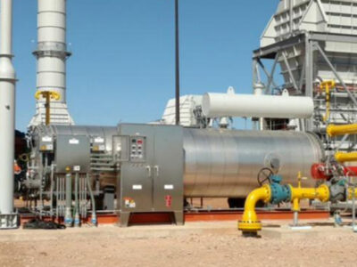
Fired heaters often receive less attention than compressors, dehydrators, or amine contactors at gas processing facilities. A large majority of fired heaters are skid-mounted, stationed on the perimeter of the unit, and often left largely ignored until an issue arises. The consequence of a tube failure, however, is usually not limited to the heater itself. A molecular (mol) sieve regeneration heater that fails can take the dehydration train down with it, and a hot oil heater failure may affect every service the loop supports. In many cases, the cost of lost throughput exceeds the cost of the repair by a wide margin.
Fired heaters are often treated as part of a utility system due to the process fluids they contain, resulting in less frequent or less effective inspection efforts which leave gaps in the integrity program. Refinery heaters are often supplied with tubeskin thermocouples, supported by a dedicated furnace engineer, backed by years of inspection history, and included in formal inspection programs. Midstream heaters do not always have these, and in some cases lack them altogether.
The damage mechanisms that affect fired heaters are well understood, including creep/stress rupture, oxidation, thermal fatigue, and a limited number of process-side corrosion mechanisms, as described in API 571. Often missing, however, is the framework connecting operating parameters to those mechanisms and directing inspection coverage to where damage is likely to occur. API 573, Inspection of Fired Boilers and Heaters, was developed primarily around refinery heaters and utility boilers, but much of its inspection methodology and tube reliability assessment approach applies to midstream equipment with some modification.
Midstream Fired Heater Services
The following services account for most fired heaters found in gas processing and treating facilities:
- Molecular sieve regeneration
- Hot oil (heat transfer fluid)
- Glycol regeneration
- Amine regeneration
- Boiler feedwater and steam generation
- Inlet gas and condensate heating
Mechanical arrangements vary considerably within these services. Some units are conventional direct-fired designs with a radiant coil in a firebox and a convection section above. Others are indirect, using a fire tube submerged in the process fluid or in a heated bath, an arrangement commonly seen on glycol reboilers and inlet gas heaters. In indirect design, the flue gas is usually inside the tube and the process fluid outside, which is the opposite orientation relative to a direct-fired coil, though the underlying mechanisms tend to be the same. Amine reboilers are a special case. Most midstream amine units supply reboiler duty with steam or hot oil rather than direct firing, so fired amine reboilers are relatively uncommon, though they are still in service at some facilities.

Midstream heaters are commonly carbon steel throughout rather than higher-alloy steel due to the lower processing temperatures. However, it also means the margin between normal operation and the onset of creep damage or overheating can be narrower than expected. Carbon steel begins to lose strength in the range of 700°F (371°C), and per API 530 (Calculation of Heater Tube Thickness in Petroleum Refineries), allowable stress decreases significantly above that point. Additionally, the operating parameters of each system must also be considered. Mol sieve regeneration units cycle through heating and cooling several times per day as part of normal operation, while others in seasonal or intermittent service may sit idle for extended periods before being restarted. Where cyclic operation is present, thermal fatigue should be considered a credible mechanism in equipment that might otherwise be evaluated only for thinning.
Table 1: Common Midstream Fired Heater Services and Their Governing Integrity Concerns
| Service | Typical Arrangement | Governing Limit | Primary Damage Mechanisms |
|---|---|---|---|
| Mol sieve regeneration | Direct fired, radiant coil | Regen gas outlet temperature and nature of cyclic service | Thermal fatigue |
| Hot oil | Direct fired, radiant coil | Maximum bulk use temperature of the heat transfer fluid | Hot organic acid corrosion, fouling |
| Glycol regeneration | Indirect, fire tube in reboiler | Thermal decomposition temperature of the glycol | Aqueous organic acid corrosion, underdeposit corrosion |
| Amine regeneration | Direct fired reboiler | Amine degradation and HSAS formation temperature | Amine corrosion, erosion-corrosion |
| BFW and steam | Direct fired, radiant coil | BFW quality, Tube metal temperature | Oxygen pitting, carbonic acid corrosion, FAC |
| Inlet gas and condensate | Direct or indirect fired | Hydrocarbon quality, process heating requirement | Carbonic acid corrosion, FAC, fouling |
Damage on Both Sides of the Tube Wall
Fire Side
Any direct-fired heater exposes the tube material to flame and flue gas regardless of the process service. At elevated tube metal temperatures, creep and stress rupture become a concern. Creep is time-dependent deformation occurring at stresses below the yield strength, and it generally presents as sagging, bowing, or bulging. API 573 identifies bulging as the more serious of these indications because it is usually associated with overheating rather than with a support or alignment issue. Flame impingement is a common contributor. Direct flame contact with a tube drives local metal temperature well above the bulk value, which accelerates creep damage and local overheating at that location while the remainder of the coil may appear to be operating normally.
External oxidation is driven by the same variable. The firebox atmosphere carries excess oxygen by design, and oxidation rates increase with metal temperature. Heavy or localized scaling on carbon steel is often an indication that tubes have been operating above the intended temperature, either from overfiring or from internal fouling that reduces heat transfer into the process fluid. One practical field check is using a magnet to help distinguish an oxidation issue from a combustion issue, because iron oxide scale is magnetic, while soot and other combustion deposits are usually not.
Thermal fatigue typically initiates at the surface and propagates with each temperature cycle. It tends to concentrate at locations where thermal expansion is restrained or where materials with differing coefficients of thermal expansion are welded. In practice, these are often attachment welds, tube-to-header connections, and nozzle welds.
Fouling with associated underdeposit corrosion should also be considered on the fire side. Soot and ash deposits reduce heat transfer and can raise tube wall temperature. Flue gas dew point corrosion is a separate concern, though it is less an issue in midstream service, where convection sections are uncommon. Furthermore, if there is sulfur present in the fuel gas, sulfate deposits can form on the tube exterior. While relatively benign during normal operation, these sulfate deposits can absorb moisture on cooldown and hydrolyze, forming sulfuric acid. As a result, shutdowns and idle periods have the potential to present a higher risk for this mechanism than normal operation.
Process Side
In general, the internal mechanism follows the service. Hot oil and glycol can both degrade thermally to form organic acids. Amine systems introduce high-temperature amine corrosion, acid gas flashing at the hot outlet, and attack associated with heat stable salts. Boiler feedwater and steam service involves oxygen pitting, carbonic acid corrosion, and scaling. Erosion-corrosion may be present in any of these services where velocity and turbulence are sufficient to disturb protective scale. Because the internal environment varies considerably between services, an in-depth damage mechanism review should be performed for each heater to assign credible mechanisms to the tube ID. This review should account for the service, operating conditions, tube metallurgy, and past inspection history, forming the basis for both the inspection plan and the IOWs discussed later.

Burner-Side Integrity
Tube Metal Temperature
The practical limit is generally the lower of the tube design metal temperature and the temperature at which the material’s allowable stress becomes controlling. A limit in the range of 750°F (399°C) is sometimes applied to carbon steel radiant tubes as a general guideline, though the appropriate value should come from the design documentation rather than a rule of thumb. Tubeskin thermocouples are uncommon on midstream heaters, so tube metal temperature is typically obtained using a handheld IR pyrometer through sight ports. Readings taken at consistent locations and intervals provide a low-cost means of trending temperatures.
Air-to-Fuel Ratio
Excess air in the range of 15% to 20% is often used as a target for complete combustion without overfiring, corresponding to approximately 3% to 4% O₂ in dry flue gas for natural gas firing. Operating below this range can result in incomplete combustion resulting in soot and carbon depositing on the tubes. Conversely, operating above these ranges increases flame temperature and flue gas mass flow, which can accelerate oxidation and reduce thermal efficiency.
Flame Character and Impingement
Flames should be stable, evenly shaped, and consistently positioned. Burner flames should be checked at a specified interval to confirm even flame characteristics and verify no impingement (flame in direct contact with the tube) is occurring. Flame impingement produces localized overheating, which can contribute to both creep damage and oxidation. One practical approach is posting reference photographs at the heater showing acceptable and unacceptable flame appearance, which helps make the assessment more consistent across operating crews.
Stack Temperature and Efficiency
Flue gas exit temperature commonly runs 100°F to 150°F (38°C to 66°C) above the process inlet temperature, though the appropriate value is specific to the heater and its duty. A decrease may indicate incomplete combustion or fouling and sustained low stack temperature can increase the risk of acid condensation in the upper stack if a convection section is present. An increase may indicate excess air or fouled tubes. Furnace external skin temperature is also worth trending, since a gradual rise can indicate refractory degradation.
Fuel Gas Quality
Fuel gas at most midstream facilities is supplied from a relatively clean source, so burner fouling is not usually a leading concern. Where contaminants are present, however, the associated problems can persist. API 573 identifies liquid and aerosol carryover as a common cause of burner tip plugging, along with amine carryover, heavier hydrocarbons, and scale in the fuel lines. Liquid reaching the burners may flash and coke the tips, and plugged tips can produce unstable flames and impingement, which returns the problem to the tubes. A common remedy in areas where this has been an issue is a coalescer downstream of the fuel gas control valve.
Service-Specific Considerations
Molecular Sieve Regeneration
Regeneration gas is commonly heated into the 450°F to 600°F (232°C to 316°C) range, depending on the system, with the beds cycling between adsorption and regeneration. Ramp rate and cycle count are the primary drivers of fatigue exposure. Manufacturers often recommend a heating and cooling rate on the order of 150°F/hr (66°C/hr), and annual cycles should remain within the design basis of both the heater and the dehydrator vessels. Where cycle counts are uncertain or believed to have been exceeded, a fatigue assessment per API 579-1/ASME FFS-1 can estimate remaining cycles. PT, MT, and phased array UT at tube-to-header welds, attachment welds, and vessel nozzle welds are among the more practical detection methods.

Hot Oil
The controlling limit is generally the maximum bulk use temperature of the specific heat transfer fluid, which varies considerably between products. Operating above manufacturer-suggested limit may degrade the fluid and can produce organic acids. Total acid number (or TAN) testing is recommended at least annually for trending in comparison to observed corrosion in the system. Oxygen ingress accelerates degradation, and an inert blanket on the expansion or surge tank is often used to limit it. Sludge and solids formation is a secondary path, where deposits foul the tube internals, raise wall temperature, and move the tube toward the creep and oxidation conditions described above.
Glycol Regeneration
As discussed, many triethylene glycol (TEG) reboilers use an indirect fire tube design. TEG begins to decompose thermally in the vicinity of 400°F (204°C), producing organic acids that lower system pH and can increase corrosion rates. Since the fire tube has flue gas on the inside and glycol on the outside, fouling on the glycol side reduces heat transfer away from the tube, and localized fire tube overheating is a common failure mode in these units. Parameters worth trending include pH, iron content, total suspended solids, and glycol color. Each of these can give an early indication that conditions in the system have changed.
Amine Regeneration
MDEA-based solvents are very common in midstream treating plants, though as noted earlier, direct fired amine reboilers are relatively uncommon. Where one is in service, the combination of amine solution and the elevated temperatures reached in the reboiler should be expected to produce some degree of corrosion on carbon steel tubes. Reboiler outlet temperature is often limited to ~260°F (127°C) to control thermal degradation and heat stable amine salt (HSAS) formation, although applicable limits may depend on the solvent blend and supplier recommendations. Amine quality plays a significant role. Lean and rich amine loading, HSAS, chlorides, iron, and amine strength are variables critical to integrity in these fired reboilers, and they are typically trended monthly or quarterly with limits established from supplier recommendations and unit operating history. Corrosion observed elsewhere in the amine unit is a useful indicator, since conditions producing metal loss in the regenerator, lean/rich exchangers, or associated piping will often produce corrosion on the fired reboiler tubes as well. Additionally, velocity through the reboiler tubes is often limited to reduce erosion-corrosion at bends and fittings.
Boiler Feedwater and Steam
Corrosion in this service is largely water chemistry driven and includes oxygen pitting, carbonic acid attack from CO₂, scale formation from dissolved solids, and flow-accelerated corrosion in turbulent regions. The primary controls are maintaining pH in the mildly alkaline range, holding dissolved oxygen in the low PPB (parts per billion) range, and controlling dissolved solids through blowdown. Deposits warrant particular attention because scale reduces heat transfer and can lead to the same overheating conditions seen in other services.
Setting Integrity Operating Windows
Integrity operating windows (IOWs) provide the link between how a heater is operated and how its mechanical integrity is impacted. API 584 supplies the framework, classifying limits as critical, standard, or informational based on the speed at which an exceedance may threaten integrity and the potential severity of the consequence. Several aspects are worth noting for midstream fired heater applications.
First, limits are unit specific. The values provided in this article and in Table 2 are representative starting points drawn from industry practice and supplier guidance and are not intended to transfer directly between facilities. A limit appropriate for one solvent, heat transfer fluid, or tube design may not suit another. A frequent issue in IOW development is adopting values from another site without reconciling them against the design conditions, materials of construction, and process chemistry of the equipment in question.
Second, it is useful to separate burner-side windows from process-side windows. Fire-side parameters such as tube metal temperature, excess air, flame character, stack temperature, and furnace skin temperature are applicable to most direct-fired heaters at a facility and can often be developed once and applied across similar units. Process-side parameters are more service specific and usually need to be developed unit by unit.
Finally, an IOW is only effective if a response is defined. Each limit should have an associated consequence, an operating action, an inspection action, and an assigned owner. Without these, the document tends to function as a record rather than as a working control.
Table 2: Representative Midstream Fired Heater IOW Parameters
| Parameter | Typical Basis for the Limit | Response on Exceedance |
|---|---|---|
| Tube metal temperature | Lower of the tube design metal temperature and the material creep threshold | Reduce firing, verify flame pattern and distribution, IR survey |
| Excess air (flue gas O₂) | Complete combustion without overfiring; commonly 15–20% excess air, roughly 3–4% O₂ dry basis | Adjust air and fuel flow, combustion efficiency test, inspect tube OD for oxide scale or soot |
| Flame character | Stable, well-defined flame with no tube impingement | Correct burner and register setting, clean tips, IR check for local hot spots |
| Stack temperature | Heater specific; commonly 100–150°F (38°C to 66°C) above process inlet temperature | Low: check for incomplete combustion and stack dew point corrosion. High: check excess air and convection fouling |
| Process outlet temperature | Degradation threshold of the process fluid (solvent, glycol, heat transfer fluid) | Reduce duty or increase process flow; sample fluid for degradation products; inspect hot outlet piping and tubes |
| Fluid quality indicators | Supplier guidance adjusted to unit history (TAN, HSAS, pH, iron, dissolved oxygen, solids) | Investigate source, adjust chemistry or replace inventory, and increase inspection at high-temperature and turbulent locations |
Limits shown are typical starting points and should be reconciled against unit-specific design and process conditions.
Inspection: On-Stream and at Outage
On-Stream
Routine operator rounds at the sight ports, covering flame pattern, impingement, and general tube appearance, tend to identify a significant portion of developing problems. Handheld IR pyrometer readings provide tube metal temperatures and can identify hot spots should there be any in the furnace. Infrared results are sensitive to emissivity, distance to target, and stray radiation, so surveys should be performed by trained personnel and compared against prior results rather than evaluated in isolation. External scanning of casing and stack can also identify refractory degradation without opening the unit.
At Outage
Internal inspection begins with a thorough visual examination of the coil for bulging, sagging, bowing, scale, spalling, and external corrosion. Directing a flashlight along the length of a tube is a practical method for identifying bulges that may not be apparent from a standing position. Wall thickness measurements are also taken. For CML density, API 573 suggests as a starting point approximately three points per tube, or readings every 5 to 6 feet, with additional coverage in more corrosive services. Circumferential band readings can detect longitudinal grooving that individual spot readings may miss, and return bends generally warrant their own condition monitoring locations (CMLs), since the required thickness for a short radius bend can exceed that of the adjacent straight tube and the outer radius often thins preferentially. Strapping for diametral growth can be useful where creep is a credible mechanism, though the tube OD needs to be cleaned to sound metal first. PT or MT at welds and attachments may be recommended for heaters in cyclic service.

Baseline thickness readings at installation are worth obtaining where possible. Without them, corrosion rates after the first inspection interval rely on the assumption that tubes were supplied at nominal thickness, which is not always the case. Inspection scope should also extend beyond the tubes. Supports and hangers, casing, refractory, tube sheets, burner tiles, and the stack are all subject to degradation, and a failed tube support is a common cause of sagging that may otherwise be attributed to overheating.
Idle Periods
Heaters in seasonal or intermittent service may be down for extended periods, and layup should be planned accordingly. API 573 recommends protecting idle fired heaters using heat, desiccants, inert atmospheres, or protective compounds. The primary mechanism of relevance here is the dew point mechanism discussed earlier, since sulfate deposits that are benign at operating temperature can become acidic once they cool and take on moisture. Damage occurring during an idle period is often not identified until the next inspection.
Conclusion
Midstream fired heaters often represent single points of failure, operating with narrower material margins and more thermal cycling than the refinery equipment around which much of the existing inspection guidance was developed. The fire side is common to these services and generally offers the most accessible reliability improvements through control of tube metal temperature, air-to-fuel ratio, flame character, and fuel gas quality. As discussed on the process side, the controlling limit frequently relates to the temperature at which the process fluid begins to degrade. Linking those parameters to damage mechanisms through a properly developed set of IOWs and directing inspection to where those mechanisms are expected to occur provides a reasonable basis for improving heater availability.
References
- API RP 571, Damage Mechanisms Affecting Fixed Equipment in the Refining Industry
- API RP 573, Inspection of Fired Boilers and Heaters, 5th Edition, April 2026
- API RP 580, Risk-Based Inspection
- API RP 584, Integrity Operating Windows
- API RP 970, Corrosion Control Documents
- API 579-1/ASME FFS-1, Fitness-For-Service ASME Boiler and Pressure Vessel Code, Section VIII, Division 2