API 579-1/ASME FFS-1 (API 579) [1] is the industry accepted international code used to make run, repair, replace decisions for in-service equipment. The fitness-for-service (FFS) procedures in API 579 have traditionally been used in a reactive mode; however, there are many opportunities to utilize FFS technology proactively. Probably the most common application of proactive FFS assessment is a brittle fracture assessment. Part 3 of API 579 is dedicated to the evaluation of existing equipment for brittle fracture. For all assessment Levels, a critical exposure temperature (CET) is compared to a minimum allowable temperature (MAT) to determine acceptability. The CET represents the driving force for fracture and consists of the lowest potential metal temperature from all operating, upset, or atmospheric conditions. The MAT represents the material resistance to fracture. The MAT for a pressure vessel or piping system is the highest (i.e., warmest) value of the MAT for any of its components. For reactors and other equipment operating in a hydrogen environment, the term minimum pressurization temperature (MPT) is sometimes substituted for the MAT.
A brittle fracture assessment may become necessary for any of the following scenarios:
- Brittle fracture was not formally addressed in the original equipment design (e.g., equipment built prior to 1987)
- Process hazards review identifies scenarios where process temperatures can fall below original design considerations (e.g., auto-refrigeration, upsets, pressure relief, etc.)
- Change in process operating conditions (e.g., re-purposed equipment, etc.)
- Re-rating or FFS for other damage
- Start-up/shutdown optimization
- Hydrostatic pressure test
- Repairs or alterations (with or without hydrostatic pressure tests)
There are three (3) key components that drive susceptibility to brittle fracture failure in carbon and low-alloy steels:
- Stress (residual and/or applied): Stress provides the energy necessary to drive a defect to fracture. Typical sources for stress include pressure, weight, and thermal loads, in addition to residual stress from the welding processes. A post-weld heat treatment (PWHT) operation will significantly reduce weld residual stress.
- Material fracture toughness: Fracture toughness is the ability of a material to absorb energy and plastically deform without fracturing. It is a function of material strength, ductility, chemistry, grain size, and heat treatment. Most pressure equipment and piping that are utilized in the oil & gas and petrochemical industries are constructed of carbon or low-alloy steel. For these materials, the fracture toughness is a function of metal temperature. At low temperatures, the material tends to behave in a brittle manner and has a high susceptibility to fracture. At high temperatures, the material tends to behave in a ductile fashion. The material fracture toughness of some materials can be altered (i.e., degraded) by the operating environment.
- Crack-like defect (size and location): Defects can result from environmental damage (such as wet H2S or caustic exposure), mechanical damage (such as gouges, dents, or fatigue), or from original fabrication (such as laminations, lack of fusion, lack of penetration, slag inclusions, porosity, etc.).
Scenarios or circumstances that tend to have an increased risk of brittle fracture failures in the oil & gas and petrochemical industries include:
- Start-ups and shutdowns
- Weld repairs, particularly repairs without PWHT
- Depressurization with liquid petroleum gas (LPG) present
- Lowering pressure below liquid hydrocarbon boiling point
- De-pressuring before draining liquids
- Equipment malfunction (relief valve failing, etc.)
- Flashing across flow obstruction when the downstream pressure is below the LPG boiling point, such as during the following:
- Leaking isolation block valve
- Manually letting down LPG into a flare header
- Overfilling a vessel and having the gas out control valve flash LPG to downstream equipment
- Operational upsets
- Overfilling vessels or drums
- Back-flowing material via a common header (flare system, liquid drain header, or recycle header)
- Recycling material back from a higher-pressure source
- Loss of reboiler heat input on a distillation column
- Hydrostatic or pneumatic tests
CASE STUDY EXAMPLES
The following case studies are provided to illustrate the benefits of performing brittle fracture screening assessments on pressure equipment and piping.
Case Study 1: Clad-Lined Reactor Susceptible to Hydrogen Embrittlement and Temper Embrittlement
Background Information:
API 579 paragraph 3.2.3 states, “If environmental cracking or a service condition that may result in a loss in the material toughness is possible, the Level 3 procedures of this Part should be utilized in the assessment.” For low-chrome equipment operating in high-pressure, high-temperature hydrogen service environments, special considerations are required in determining the MAT, specifically (1) embrittlement caused by the hydrogen charging and (2) long-term temper embrittlement. Dissolved hydrogen can lead to embrittlement of the steel, which can manifest itself in two ways: (1) increased susceptibility to fast fracture due to a reduction in toughness and (2) susceptibility to subcritical hydrogen-assisted crack propagation, or ‘slow fracture.’ Both fast-fracture and slow-fracture failure modes must be accounted for in developing permissible pressure-temperature operating envelopes. Additionally, temper embrittlement of low-chrome materials can further degrade toughness. According to API 571 Damage Mechanisms Affecting Fixed Equipment in the Refining Industry [2], temper embrittlement is defined as the reduction in toughness due to a metallurgical change that can occur in some low-alloy steels as a result of long-term exposure in the temperature range of about 343°C to 577°C (650°F to 1070°F). This change causes an upward shift in the ductile-to-brittle transition temperature. Although the loss of toughness is generally not evident at operating temperature, equipment that is temper-embrittled may be susceptible to brittle fracture during start-up and shutdown. The following figure shows the typical MAT curve for 2.25Cr. equipment exposed to hydrogen:

The following is a summary of critical design data associated with a hydroprocessing reactor that an owner-operator intended to optimize start-up and shutdown limits:
- Code of Construction: ASME Section VIII, Division 2 Code (ASME VIII-2)
- Year Built: 1987
- Design Pressure: 2062 psig
- Design Temperature: 850°F
- Radiography: Full (100% joint efficiency)
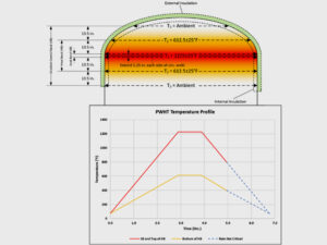
- PWHT: Yes (8.1 hours at 1275°F)
- Impact Test: 40 ft-lbs average, 35 ft-lbs minimum at -20°F
- Materials of Construction:
- Shell: SA-336 Grade F22 (2.25 Cr-1 Mo)
- Overlay/Cladding: TP309L/TP347SS
- Inside Diameter: 13 feet, 6 inches (162 inches)
- Nominal Shell Base Metal Thickness: 8.07 inches
- Nominal Head Base Metal Thickness: 4.06 inches
- Corrosion Allowance: 0.25 inches (309L/347SS overlay)
The operating conditions for the reactor are summarized below:
- Operating Pressure: 1700-1900 psig
- Operating Temperature: 680-740°F
- Hydrogen Partial Pressure: 1815 psia at 740°F
Assessment Methodology:
Given the operating environment, API 579 Part 3 Level 1 and Level 2 MAT screening procedures were not applicable. Therefore, an API 579 Part 3 Level 3 brittle fracture evaluation was completed using the failure assessment diagram (FAD) fracture mechanics approach presented in API 579 Part 9. The applied primary, secondary, and weld residual stresses are used along with material strength and material fracture toughness to calculate a toughness ratio, Kr, and load ratio, Lr. These two quantities represent the coordinates of a point that is plotted on a two-dimensional FAD to determine acceptability. Because material fracture toughness, Kmat, is a function of temperature, the FAD assessment can be iteratively solved to develop a curve of permissible pressure-temperature combinations.
- Stress: The assessment included evaluation of primary stress due to pressure, weld residual stress (with credit for PWHT) per API 579 Annex 9D, and secondary stress from differential thermal expansion between the weld overlay material and the base material using the guidance in WRC Bulletin 562 [3].
- Material Fracture Toughness: The lower-bound Wallin Fracture Toughness Master Curve (Master Curve) toughness correlation for quasi-static loading conditions with a 5% probability of failure target (Pf) from API 579 Annex 9F was employed to estimate the material fracture toughness as a function of temperature. Adjustments were made to account for temper embrittlement and hydrogen embrittlement using the guidance in API 579 Annex 9F and Annex 9J.
- Reference Flaw Size: The MAT/MPT assessment was completed using a conservative postulated reference flaw depth of 1 inch and a flaw length of 6 inches (i.e., 6:1 aspect ratio).
Assessment Results:
The results from the MAT/MPT assessment for a 1-inch-deep postulated reference flaw are summarized in the figure below.

The results from the fast-fracture portion of the MAT/MPT assessment were significantly less restrictive than the previous MAT/MPT that was being utilized by the owner-operator. However, results from the slow, stable crack growth assessment limit the MAT/MPT for a portion of the operating pressure range. Atomic hydrogen at a crack tip can promote slow, stable crack growth at a hydrogen-affected threshold stress intensity level ( KIH), below the hydrogen-free plane strain fracture toughness ( KIC) for steel. Slow, stable crack growth can occur through:
- concentrated hydrogen in the plastic zone at the crack tip when the steel cools
- the presence of high-pressure hydrogen in the crack tip environment at lower temperatures
Slow, stable crack growth is incremental, occurring on a small-length scale, during each start-up/shutdown cycle. As a result, several cycles would typically be needed before a significant and potentially unstable crack would be present. Therefore, restricting the MAT/MPT curve to completely eliminate potential for slow, stable crack growth during start-up and shutdown can be overly conservative when establishing operating limits for some equipment. Many owner-operators mitigate concerns for slow, stable crack growth through inspection programs. For this reactor, the owner-operator reestablished its operating limits based on the MAT/MPT results for fast fracture, and they implemented an optimized inspection plan to address any potential concerns for slow, stable crack growth. Using the new MAT/MPT limits, the owner-operator was able to drastically reduce the timing for future unit start-ups without sacrificing safety.
Case Study 2: Piping Assessment to Evaluate CET Conditions Colder Than Original Design MDMT
Background Information:
A process hazards review identified process conditions that could fall below, or at temperatures colder than, the minimum design metal temperature (MDMT) for a section of piping. An API 579 Part 3 Level 3 assessment was completed to evaluate CET conditions less than the MDMT.
The following is a summary of critical design data associated with a section of piping that an owner-operator intended to understand the risk for brittle fracture at temperatures less than the MDMT:
- Code of Construction: ASME B31.3
- Design Pressure: 150 psig
- Design Temperature: 20°F to 150°F
- Radiography: Full (100% joint efficiency)
- PWHT: No
- Materials of Construction:
- Pipe: A-53-B (Curve B)
- Flange: A-105 (Curve A)
- Fittings: A-234-WPB (Curve B)
- Components: NPS 8 STD Pipe, Class 150 Flanges
Assessment Methodology:
An API 579 Part 3 Level 3 brittle fracture evaluation was completed using the FAD fracture mechanics approach presented in API 579 Part 9 to create an MAT curve for the section of piping that was flagged for having a potential of exposure to temperatures less than the design MDMT of 20°F. Similar to the Case Study 1, the applied primary, secondary, and weld residual stresses are used along with material strength and material fracture toughness to calculate a toughness ratio, Kr, and load ratio, Lr. These two quantities represent the coordinates of a point that is plotted on a two-dimensional FAD to determine acceptability. Because material fracture toughness, Kmat, is a function of temperature, the FAD assessment can be iteratively solved to develop a curve of permissible pressure-temperature combinations.
- Stress: To quantify forces, moments, and stresses in the piping system attributed to internal pressure, weight, and thermal expansion/contraction, a piping flexibility analysis was performed using E2G’s proprietary SIMFLEX-IV software. The piping flexibility model extended beyond the regions of concern to ensure that piping stresses were properly represented. Hoop and longitudinal stresses due to internal pressure were evaluated along with longitudinal stress for sustained and thermal expansion loads as determined from the piping flexibility model. Weld residual stress was also included in the evaluation for the as-welded condition per API 579 Annex 9D. Iteration is required to accurately quantify the piping weight and thermal expansion/contraction stresses as a function of temperature (and support activity). A custom E2G script was used to iterate the piping flexibility model to establish the full range of permissible MAT vs. pressure combinations.

- Material Fracture Toughness: The lower-bound Master Curve toughness correlation for quasi-static loading conditions with a 5% probability of failure target (Pf) from API 579 Annex 9F was employed to estimate the material fracture toughness as a function of temperature.
- Reference Flaw Size: As recommended by API 579, a semi-elliptical surface-breaking flaw with a depth equal to 25% of the nominal thickness (i.e., t/4 flaw) or 0.125 inches, whichever is greater, and a length of 6 times the depth was assumed for the analysis. Additionally, a flaw with a maximum depth of t/8 or 0.0625 inches (whichever is greater) was evaluated.
Assessment Results:
The results from the MAT assessment for the postulated reference flaws are summarized in the figure below.

The results from the Level 3 MAT assessment indicate that the MATs for 0.125-inch-deep and 0.0625-inch-deep flaws are lower (i.e., colder) than the original design MAT of 20°F. Operating points falling to the right and below the MAT curves are considered acceptable. For a 0.125-inch-deep flaw, a pipe-to-flange connection at a circumferential weld near a valve connection is the limiting component, and for a 0.0625-inch-deep flaw, a pipe at a circumferential weld near a tee junction is the limiting component.
When a Part 3 Level 3 MAT evaluation is used to qualify equipment or piping for protection from brittle fracture, it is expected that the equipment or piping is properly inspected for any crack-like indications. The inspection methods, accuracy, and precision must be suitable for the reference flaw sizes determined to be acceptable in the FFS evaluation. To supplement the FFS results, it is recommended that an inspection plan be developed and implemented to confirm that no significant crack-like flaws exist or develop over time.
SUMMARY
This article highlights the advantages of completing a brittle fracture screening assessment on pressure equipment and piping. Case study examples were provided to demonstrate the benefits of using a fracture mechanics-based approach, which is recognized to be the most accurate and most reliable means to determine low-temperature operating limits for pressure equipment and piping. For more information related to fracture mechanics-based procedures for brittle fracture screening, please refer to WRC Bulletin 599 [4]. The bulletin was recently published by E2G, and at the time this article was published, the alternate procedures presented in WRC Bulletin 599 were being reviewed by the ASME/API Joint Committee on FFS for incorporation into a future release of API 579.
REFERENCES
- API/ASME, 2021. API 579-1/ASME FFS-1 Fitness-For-Service. The American Petroleum Institute and The American Society of Mechanical Engineers, Washington, D.C./New York.
- API, 2020, API Recommended Practice 571, Damage Mechanisms Affecting Fixed Equipment in the Refining Industry. The American Petroleum Institute, Washington, D.C.
- Osage, D., Spring, D., Anderson, T., Kummari, S., Prueter, P., and Wallin, K., 2017. Welding Research Council Bulletin 562: Recommendations for Establishing the Minimum Pressurization Temperature (MPT) for Equipment. Welding Research Council, New York.
- Macejko, B.R., Kummari, S.R., Osage, D.A., 2023. Welding Research Council Bulletin 599: Recommendations for Evaluating Resistance to Brittle Fracture for Carbon and Low Alloy Steel Equipment and Piping. Welding Research Council, New York.