Note: This article is intended to provide a general overview of the API 579 Part 11 Fire Damage Assessment methodology.
Unfortunately, industrial fires can occur despite our best efforts. The fires can occur in any industrial setting from downstream refining to midstream, petrochemical, and fertilizer facilities; offshore platforms; tank farms; etc. When a fire does occur, the first priority is always the safety of plant personnel, surrounding community, and environment. Of course, the next priority is safely extinguishing the fire. However, once the fire has been extinguished, and everyone’s safety is confirmed, attention shifts to the eventual re-commissioning of the affected components, which can range from a confined location within a process unit up to an entire site. The goal of the fire damage assessment is to methodically evaluate affected components (piping, fixed equipment, structural steel, etc.) and ultimately determine what can be safely re-used and what may require repair or replacement. In general, experienced subject matter experts (SMEs) familiar with fire damage assessments should be involved throughout the entire process, whether the SMEs are provided internally or with assistance from a third party.
The First Steps
The first step of a fire damage assessment is typically the evidence gathering stage, which may be performed in conjunction with the general incident investigation team. The goal of evidence gathering is to determine the root cause of the fire. Plant security/surveillance may have captured pictures or videos of the initial leak and subsequent ignition, and eyewitness accounts from plant personnel may provide additional insight, but ultimately the origin of the fire needs to be understood. Once the origin is found, heat exposure zone (HEZ) maps (Figure 1) are created to further define the initial scope of the fire damage assessment. HEZ maps establish temperature zones in any given location to indicate the temperature(s) to which components were exposed during the fire. Table 1 summarizes commonly accepted HEZs. For a given HEZ, a likely exposure temperature and possible effects of damage as a result of this exposure are documented. For example, Table 2 provides fire damage effects of components exposed to HEZ IV. Note that if multi-level platforms were exposed to the fire, the investigation needs to consider elevation as well.
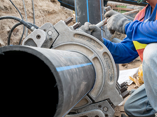
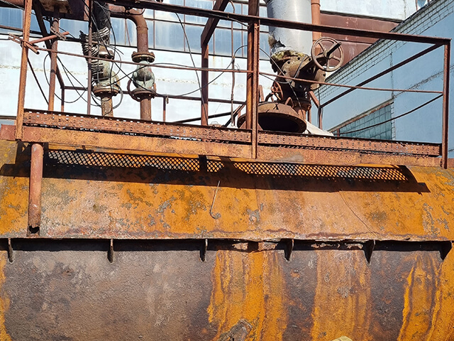
Once a qualified engineer has concluded that it is safe to do so, site walk-downs are typically involved in establishing HEZs. Evidence such as blistered painting, melted insulation jacketing, melting of light bulbs, thermal distortion of piping/structural supports, etc. can provide insight on the likely temperature exposure in a given zone. API 579 provides a comprehensive list of evidence “cues” to evaluate during site walk-down to help define HEZs. An example of a common scenario encountered during a site walk-down is provided in Figure 2. It is critical to emphasize that HEZ maps only provide descriptions of approximate maximum flame temperature. While this evidence provides information on likely HEZs, the fitness-for-service (FFS) evaluation must ultimately consider metal skin temperature rather than flame temperature. For example, piping containing large amounts of water (e.g., CTW, some amine piping) compared to piping containing predominantly hydrocarbon will experience significantly different metal skin temperatures, despite exposure to the same flame temperature, because the process side will absorb different amounts of heat. Pool fires and jet fires will also result in significantly different HEZs for a given component.


Understanding the Effects of Fire Damage
Understanding the many different effects of fire exposure on a given component is highly dependent on the assigned HEZ. As typically occurs in HEZ V or VI, when carbon steel and low-alloy steels are exposed to temperatures above their critical temperature (which is dependent on microstructure/chemical composition), the pre-existing microstructure may be compromised, particularly if it was quenched from this temperature as a result of fire water. This can result in significantly altered material and physical properties relative to original installation. If a component was originally post-weld heat treated (PWHT’d), it is possible that the fire exposure “erases” the beneficial effects of the original PWHT (hardness reduction and minimizing weld residual stress). Even if a component was not originally PWHT’d but instead normalized and tempered (e.g., CS) or solution annealed (e.g., 300 stainless steel), the fire exposure may still “erase” the effects of the heat treatments. Note that flange bolting generally has specific heat treatments that may also be “erased” due to fire exposure. Gaskets can be similarly compromised.
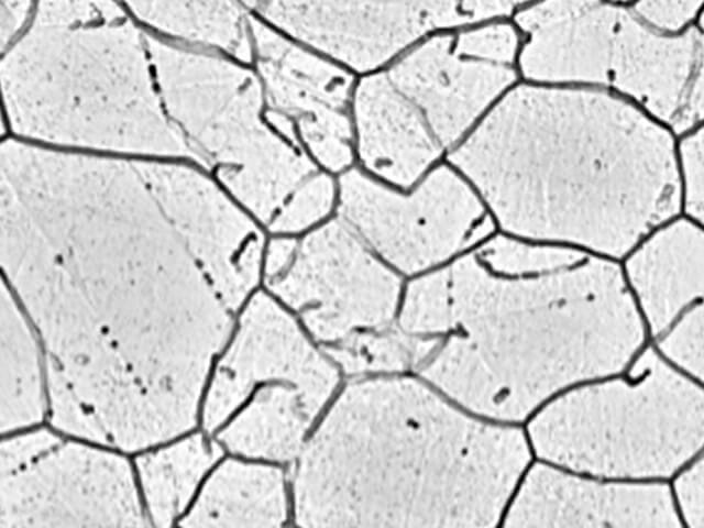
Some materials can experience grain growth, which may also negatively affect material properties. Structural steel (e.g., I-beams) can experience sagging/distortion (Figure 3) and/or decarburization, effectively removing the steel’s structural strength. Austenitic stainless steels (e.g., 300-series SS) can be sensitized if exposed to a high enough temperature (Figures 4 and 5). Sensitization generally negatively impacts corrosion resistance, and the component may no longer be suitable for the intended service. In addition, fire water may contain high concentrations of chlorides, which can potentially cause chloride stress corrosion cracking of austenitic stainless steels. Thermal expansion of components (especially piping) during exposure to the fire may have caused damage if the existing piping supports could not adequately support this loading. This is not an exhaustive list of all the possible effects from fire damage. Rather, several examples are included for information, illustrating the necessity of involving an experienced SME in any fire damage assessment. In general, the API 579 Part 11 FFS methodology is intended to quantify these possible negative effects (and more).


API 579 Part 11 Fire Damage Assessment Process
The Level 1 FFS assessment for Part 11 fire damage assessments is simply a screening criterion based on material of construction and assigned HEZ. Table 3 provides acceptable combinations of material of construction and assigned HEZ that will pass a Level 1 assessment and require no further screening. Again, it is important that the originally assigned HEZs are representative of reality based on SME expertise, or it is possible that the conclusions can be non-conservative. API 579 also provides additional Level 1 guidance for protective coatings and inspection of flanged joints and gaskets. In general, best practice is to indiscriminately replace all gaskets and flange bolting that was exposed to HEZ V or higher (some owner-users may have more stringent criteria).

As expected, the Level 2 Part 11 assessment involves a much more exhaustive study for components that did not pass the Level 1 criteria. The Level 2 assessment requires a methodical approach to evaluating the material properties of exposed equipment, piping, or structural supports and typically involves a combination of in-situ hardness testing and field metallographic replication (FMR). As previously mentioned, if a material was exposed to a metal skin temperature above its critical temperature and subsequently quenched via fire water, the original microstructure is likely not intact. This may be accompanied by an increase in hardness, for which hardness testing is typically performed for carbon and low-alloy steels. If the hardness is above the acceptable limit, follow-up FMR may be performed for verification of microstructure (e.g., martensitic microstructure in high hardness carbon steel may be present). Equipment/piping in aggressive environmental service (AES) may have originally required PWHT and a more stringent hardness criterion. If evaluated components do not satisfy this criterion, replacement of the component would be general best practice, but this may be evaluated on a case-by-case basis with support from an experienced materials and corrosion and FFS engineer. Field PWHT of affected components is a possibility, but the challenges involved with field PWHT need to be considered (e.g., structural integrity during the PWHT, properly designed full circumferential soak band, etc.) as well as further possible degradation to the microstructure from another heating cycle. In theory, hardness testing of bolting could be utilized to determine if the original material properties are still present. However, practically, in-situ hardness testing of bolting will likely be limited by the bolting diameter and available surface area. FMR may also be used to identify potential decarburization of structural steel (and subsequent loss of strength) and/or grain growth of carbon steels which may lead to degraded properties.
In general, austenitic stainless steels are not hardenable via heat treatment or from exposure to fire; thus, hardness testing is generally not utilized for these materials. However, exposure of austenitic stainless steels to high temperatures during a fire event can degrade the microstructure, effectively eliminating corrosion resistance. This can often be accompanied by sensitization of the microstructure and would be determined via FMR. Some austenitic stainless steels are solution annealed during fabrication, and this heat treatment may have been “erased” due to fire exposure and would also likely be determined via FMR interpretation. The Level 2 fire damage assessment should also include inspection of piping supports to ensure they are in the as-designed condition and were not overloaded from thermal expansion during the fire. For austenitic stainless steel piping exposed to the fire, it is good practice to perform dye penetrant testing (PT) of pipe support welds, anchor points, saddle supports, etc. to verify integrity. Figure 6 shows a (fortunately) successful example of PT inspection with no indications observed. This testing may be prioritized based on assigned HEZ. PT should also be performed on tube-to-tubesheet welds (especially for fixed-fixed tubesheet HXs), again prioritized based on assigned HEZ.

A Level 2 assessment will typically include miscellaneous items not directly related to hardness testing or FMR. For example, internal attachment-to-shell welds where large thermal gradients could have occurred should be inspected for cracking. If hardness testing results are out of specification, rerates of fixed equipment may be required based on potential reduction of strength. Note that the expected “new” corrosion rate (if applicable) would also be considered during the rerate. On occasion, an API 579 Part 10 Level 2 creep damage assessment may accompany the fire damage assessment for severe exposure of some components. Finally, Level 3 assessments are generally reserved for the most severe damage of long lead-time components where a required replacement would significantly delay recommissioning. For example, finite element analysis (FEA) of shell distortion could be a candidate for a Level 3 assessment. This assessment also needs to consider the potential change in material properties as a result of exposure to the fire as well as any potential changes in expected corrosion resistance.
Planning Ahead
No facility ever intends to require a fire damage assessment, and, thus, it can be difficult to plan for one. However, it is prudent to consider the general framework that would be required ahead of time should the need ever arise, which means having a plan in place that documents the required resources and personnel. Once the safety of the site and the community is established, an efficient fire damage assessment method can significantly reduce downtime and minimize production losses. Efficient record/documentation maintenance is important to understand what components are in the field and have a baseline for comparing test results. E2G understands that time is of the essence and has delivered emergency fire damage support on multiple occasions over the last few years. Our typical response time is 48 hours from initial contact to E2G personnel on site, although we have also provided mobilization in as little as 24 hours. E2G provides experienced fire damage SMEs to help facilitate the fire damage assessment process to deliver results and save valuable time.