Introduction
High-temperature creep is a time-dependent phenomenon characterized by gradual, continuous deformation affecting all metals and alloys under the combined action of temperature and stress. Furthermore, stress levels below the time-independent yield strength of a given material can be sufficient to cause inelastic creep deformations and damage, especially for long loading times and elevated temperatures [1]. In general, creep damage accumulation and the propensity for rupture/failure at or near welds are a function of material properties (including chemical composition, microstructure, heat treatment, strength, component geometry/constraint, and previous loading history or deformations that may be present), operating stresses, metal temperatures, and time in service. Creep damage accumulation over time can lead to void growth and crack formation, eventual rupture of pressure equipment, and failure of engineering components and structures [2]. Furthermore, it is recognized that welds are often the weak links in pressure equipment and other structures, especially at elevated operating temperatures. Factors contributing to failures of welds are well known, including residual stresses, defects or microstructural imperfections or weak zones caused by welding, loss of optimal base metal microstructures during the weld thermal cycle, toughness changes, development of ductility lowering multiaxial stress states due to dissimilar creep properties of base metal and weld deposits, deterioration of material properties that may be accelerated during high-temperature service exposure and, of course, stress amplification effects of geometrical discontinuities in the vicinity of a joint [3]. Additionally, weld misalignment or “peaking” increases the likelihood of failure and can dramatically reduce the remaining creep life of components operating at high temperatures [4-6].
As described herein, testing welded specimens and realistically simulating the creep response of welded components can offer perspective on remaining life and help quantify the risk associated with operating in-service, high-temperature equipment. To this end, predicting remaining life in pressure equipment and other engineering components subject to high-temperature creep is an extremely useful endeavor. It is also essential to understand the typical evolution of creep damage at welds and the limitations associated with different inspection techniques, whether surface-based or volumetric in nature. Also, advancements in material technology have led to the creation of more damage-tolerant and creep-resistant alloys than ever before. Creep testing of uniaxially loaded specimens represents the most common method for establishing creep properties that can be used in an engineering evaluation to predict remaining life, including advanced computational simulations on complex geometries. For fitness-for-service applications, the Omega Creep Method represents a well-documented and widely used approach for practitioners [7]. This method, based on the Materials Properties Council (MPC) Project Omega Program, is comprehensively outlined in Part 10 of API 579-1/ASME FFS-1, Fitness-For-Service (API 579) and contains a wide-ranging database of high-temperature material properties characterizing creep rupture behavior for many different alloys commonly used in the oil and gas, petrochemical, and related industries [8].
Characteristics of Weld Creep Damage
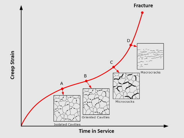
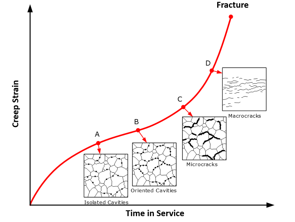
In general, pronounced creep voids, fissuring, and creep crack formation in pressure equipment may not be perceptible until the end of useful operating life is approaching, especially at the surface (e.g., if field metallographic replication [FMR] is being performed to examine microstructural characteristics). Figure 1 depicts idealized microstructural creep damage evolution as a function of creep strain and time in service (note that actual material behavior should be evaluated on a case-by-case basis). This figure reinforces the concept that over time, creep damage progresses (in order of increasing severity) from isolated voids/cavities to larger, linked-up voids, to micro-cracks, to larger macro-cracks. Moreover, macro-cracks often are not prevalent until accelerated creep damage and crack propagation are observed immediately before failure/fracture. This observation implies that in general, once widespread macro-cracks are identified, equipment replacement should be strongly considered given the risk for rapid damage progression and subsequent rupture. The challenges associated with identifying incipient creep damage make relying solely on non-destructive examination methods (including FMR) to make run-repair-replace decisions problematic since inspection intervals that are too infrequent could result in failure before noteworthy damage can be clearly identified. For this reason, leveraging engineering/fitness-for-service calculations to estimate remaining creep life can help guide inspection strategies/intervals and offer perspective on when creep damage accumulation reaches a critical threshold [2].
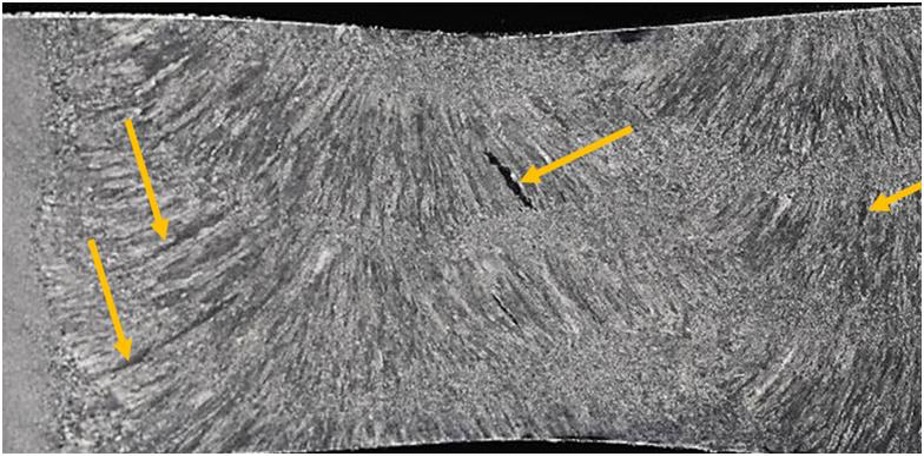
For in-service pressure equipment, inspection for creep damage should focus on welds, in general, but especially on Cr-Mo welds operating in the creep range. Welds may also contain original fabrication defects, lack of fusion, porosity, slag inclusions, etc. that often serve as damage initiation sites. Furthermore, the mismatch in material properties between weld deposits, heat-affected zones (HAZs), and adjacent base metal can increase the propensity for crack initiation and accelerate creep crack propagation. Different microstructures in the weld deposit can also lead to local differences in the stress distribution and eventual crack initiation, as shown in Figure 2. Considering 1 Cr – 1/2 Mo and 1-1/4 Cr – 1/2 Mo materials are particularly predisposed to low creep ductility, careful attention (both design and inspection activities) should be given to welded regions in these components [2]. Additionally, the extent and morphology of creep damage seen on utility piping provide information about the nature of creep cavity initiation and growth in and near welded regions. Based on extensive metallographic examinations from numerous power plants, the features of creep-related cracking in submerged arc welds in steam piping applications can be summarized as follows [3]:
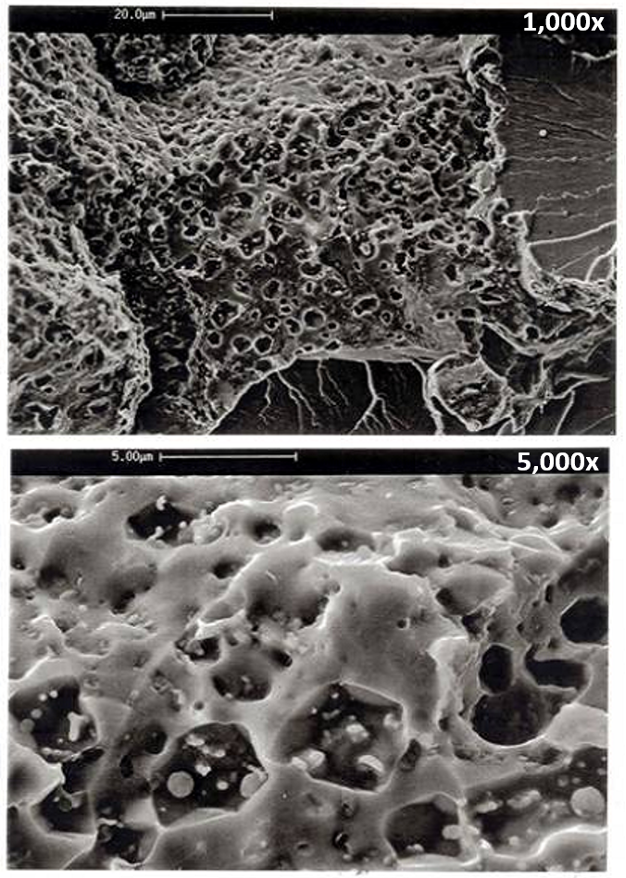
- Creep-driven voids and cavities are angular when in the isolated and aligned cavity stages. Cavities become spherical on micro-crack surfaces. Spherical-shaped cavities are usually a sign of advanced-stage and extensive cavitation (see Figure 3).
- Cavities initiate on grain boundaries and are normally associated with grain boundary particles (inclusions and carbides).
- No measurable plastic deformation typically accompanies cavity initiation and growth.
- The creep damage level is related to cavity size and distribution as a function of time.
- Cavities initiate subsurface in the weld metal and/or the HAZ and cannot be detected by replication.
- Micro-cracks are formed by link-up of progressively initiated cavities along grain boundaries. The discontinuous and staggered micro-crack pattern is largely confined to the fusion boundary or the near-fusion boundary region in the weld metal.
- Macro-cracks grow by link-up of cavities or by interconnection of adjacent micro-cracks. Final failure (leak or rupture) occurs by link-up of macro-cracks to a critical unstable size through the wall of the long seam-welded pipe in a time-dependent manner.
Listed below are some of the conclusions and lessons learned based on broad inspection experience with high-temperature (e.g., steam) piping systems [3].
- Magnetic particle inspection only sometimes provided evidence of long seam weld creep damage.
- Surface microstructure examination, usually replication, was not useful for detection of creep damage.
- Radiographic inspection did not reliably detect early long seam weld creep damage.
- Eddy current inspection did not consistently detect early long seam weld creep damage.
- Liquid penetrant inspection cannot detect subsurface long seam weld creep damage.
- Conventional ultrasonic testing (UT) inspection sometimes did detect cracks at welds that are not surface connected, but only at a very advanced level of damage.
- In general, conventional “on-cooling” acoustic emission (AE) testing is not appropriate for detection of a long seam weld creep-induced flaw growth because of excessive system noise, and cracks do not grow on cooling.
- The MPC has successfully monitored creep crack propagation at welds at temperature with AE in the laboratory and has shown the need for wave form analysis to correctly classify emissions.
- Properly implemented advanced high-sensitivity ultrasonic techniques (focused phase array) can find fusion line (Type IV) HAZ grain boundary cavitation.
- Wave form analysis (pattern recognition) methods are beneficial to identify and separate ultrasonic signals from low-level defects well before failure.
- In general, successful application of advanced UT and AE requires validation and qualification of methods, equipment, and personnel using standards made from service-damaged components that have been fully characterized.
Creep strength-enhanced ferritic (CSEF) materials are high-strength alloys constructed to exhibit favorable oxidation, corrosion, creep, and even fatigue resistance at elevated temperatures [9]. Conventional CSEF grades such as P91, P92, and P122 that contain between 9 and 12 weight percent chromium are used extensively in the power generation industry for components in supercritical steam service (e.g., superheater and reheater headers, associated piping, tubes, etc.). The high strength of these materials at elevated temperatures is an artifact of a microstructure containing tempered martensite with finely dispersed nitrides and carbides [2]. In general, CSEF steels are also micro-alloyed with vanadium and niobium with controlled nitrogen content and other micro-alloying elements. Notwithstanding the beneficial aspects of these materials, the welding process can unfavorably modify the microstructure (and properties) of the welded region and HAZ through the formation of additional martensite [9]. In general, the welding process generates an HAZ between the weld deposit itself and the base metal. The creep properties in the HAZ usually vary significantly relative to adjacent regions, and as such, this leads to multiaxial stress states, creep cavitation, void growth, crack initiation (referred to as Type IV cracking) in the HAZ, and eventually premature failure. In general, Type IV cracking is highly influenced by stress in weldments, particularly at the edge of the HAZ. Welded joint mechanical design (geometry) should avoid high stress concentrations in the weld itself and the surrounding HAZ to prolong creep life. Dissimilar metal welds (a known problem area for CSEF steels) should also be meticulously designed and inspected to mitigate in-service cracking [2].
In general, there are many confounding factors that affect the long-term high-temperature performance and longevity of welds in CSEF materials and other alloys operating in high-temperature service. These factors include but are not limited to the following:
- Different creep rates for base metal and weld deposits, i.e., “metallurgical notches” (stress concentrations) caused by creep rate mismatch of base metal and weld deposit.
- Extensive precipitation of embrittling or hardening phases in base metal and/or weld metal with increasing time and temperature.
- Stress concentrations caused by geometrical factors associated with the weld deposit.
- Differential thermal expansion between the weld deposit and base metal.
- Time-dependent volumetric changes of base metal and weld deposit due to metallurgical changes.
- Degradation of creep strain tolerance (e.g., embrittlement, loss of ductility) of the weld deposit with time and temperature.
- Development of high levels of triaxiality in the HAZ or weld deposit (facilitating void initiation and growth).
- Excessive over-matching or under-matching in selection of weld consumables.
- Over-tempering in the fine grain region of the HAZ of CSEF alloys [9-11] during welding.
- Micro-fissuring or grain boundary liquation near the fusion line that may lead to low strain tolerance in the weld HAZ (especially in highly alloyed materials).
- Embrittlement in the grain-coarsened region of the HAZ.
- Elevated creep rates associated with grain-refined regions of the HAZ.
- Creation of microstructure that is highly susceptible to creep damage during post-weld heat treatment (PWHT).
- Precipitation or diffusion near the fusion line during long-term elevated temperature exposure that can lead to ductility or strength loss associated with carbon diffusion (denudation) or carbides not seen in shorter-term exposures.
- Detrimental effect of optimizing elements to enhance ambient temperature properties (e.g., reducing carbon content, increasing manganese, nickel, etc.).
- Improper extrapolation of data from temperature accelerated tests to lower operating temperatures.
- Grain refining procedures that lead to increased creep rates, e.g., controlled deposition (“temper bead”) welding to avoid PWHT or stress relief cracking.
- Solidification cracks resulting from welding which can lead to creep crack propagation.
- Cyclic straining which can lead to strain softening and associated reduction of creep strength of CSEF alloys.
- Residual stresses combined with applied stresses accelerating creep damage and leading to failure.
- Redistribution of stresses due to differing creep rates or local damage leading to increased multiaxial stresses, void initiation, and growth.
- Diffusion of elements from the weld or base metal across the fusion line due to activity differences leading to depletion or embrittling precipitates adjacent to the fusion line.
- Weld bead placement leading to contiguous microstructures of low resistance to creep (high creep rates) and early crack initiation.
- Inclusions in the weld deposit contributing to early creep void initiation.
Creep Testing Considerations
Creep-resistant alloys intended for high-temperature service are often difficult to fabricate and require closely controlled welding procedures. Once components are placed in service, repairs and repeated inspections are often impractical and costly from the standpoint of equipment downtime (lost production). The key to obtaining reliable service is specific and appropriate qualification of welding procedures to ensure resistance to the probable types of damage that may occur to both base materials and welded joints. As thoroughly documented in Welding Research Council (WRC) Bulletin 560 [3], testing and analyzing welds for high-temperature service applications is an essential step in ensuring long-term equipment reliability. In general, tests of welds using small specimens or under conditions that do not produce the failure modes anticipated in service cannot be extrapolated for accurate life prediction. Furthermore, systematic studies of the effects of material properties and welding procedures have shown that the influence of test specimen size, creep property mismatch, and procedures for extrapolation of test results with stress and temperature are not widely understood or properly considered. The effect of specimen size is clearly shown in Figure 4, where chrome-moly alloys were examined at relatively low stress levels (note that both axes in this figure reflect a log scale). It is postulated that the observed increase in creep rupture life associated with larger specimen size is due to constraint on the soft zone deformation which, in turn, impedes plastic collapse. Furthermore, oxidation is not believed to be a significant factor in these tests. Within each set of test data shown, the failure modes were primarily the same, irrespective of specimen size. This makes the slope of the lines meaningful and indicates that larger specimens may generally produce more realistic behavior that mimics actual in-service welded components relative to smaller-scale test specimens [3].

Historically, to avoid the high cost and the notable wait time for long-term creep test results, stress-rupture studies of welds are typically conducted at increased temperatures using stresses significantly above design levels. Aside from failing to account for multiaxial loads that are encountered in actual service and the potential contribution of creep-fatigue interaction, testing well above design levels is not typically good engineering practice. Test temperatures and stresses influence the failure mode, and increasing these parameters makes proper extrapolation of the results to realistic service conditions difficult. Furthermore, test temperatures that are too high may enhance ductility and lead to overly optimistic life projections because precipitates that will occur in service at lower temperatures reduce ductility and component life, especially in the weld fusion zone [3]. Likewise, extrapolation of test results over a large temperature range introduces considerable uncertainty because of potential changes in creep damage mechanisms. To qualify a procedure for fabrication or repair welding, the stresses for transverse tests of welded joints should be close to the design allowable stresses for the applicable range of temperatures. This is necessary to ensure that the results will be relevant to weld performance in service. The specimens should be as large as practical and reflect the welding parameters to be used and the base metals to be joined and should also cover the range of strengths and microstructures in the equipment of concern. For a weld repair scenario, the base material used to prepare test specimens should be either service aged or representative of the expected aged microstructure. When testing ex-service cross-weld samples, the specimen extraction location should be representative of the other welds in the system (in terms of geometry and long-term operating stresses and temperatures). Extracting ex-service samples and performing Omega creep tests represent a beneficial way to establish material properties that account for past damage accumulation, without the need for a detailed compilation of past operating pressures and temperatures. Subsequently, material properties based on Omega test results can be leveraged in remaining life calculations to prolong equipment repair or replacement. As such, the advantages of performing Omega tests can often easily offset the costs associated with sample extraction, preparation, and testing.
Low-Chrome Peaked Pipe Failures
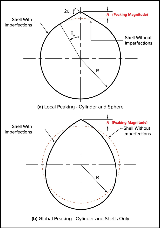
Several failures of welded high-temperature, low-chrome piping in the refining and power generation industries have been attributed to peaking of longitudinal weld seams. Generally, local weld seam peaking occurs during pipe manufacturing, where the rolled pipe locally deviates from a true circular cross section at the weld, as shown in Figure 5 (peaking can be considered either local or global as depicted). Additionally, most welded piping fabrication standards have no specific acceptance criteria for this type of weld misalignment. Furthermore, some of the high-temperature pipes that have failed conformed to the required original fabrication tolerances, but no documented peaking measurements were available in the equipment inspection files. This often makes it problematic to quantify the risk associated with elevated temperature operation of low-chrome piping. As discussed in detail in References [4-6], depending on original heat treatment, creep damage progression is known to be accelerated by the mismatch in creep properties of the weld deposit, HAZ, and adjacent base metal. This property mismatch results in stress intensification and triaxial tension that can accelerate creep damage near the weldment. Longitudinal weld seam peaking can induce significant local bending stresses in the pressure boundary, and for piping components that operate in the creep regime, the presence of local peaking can lead to an increased tendency for creep crack initiation, propagation, and eventual catastrophic rupture.
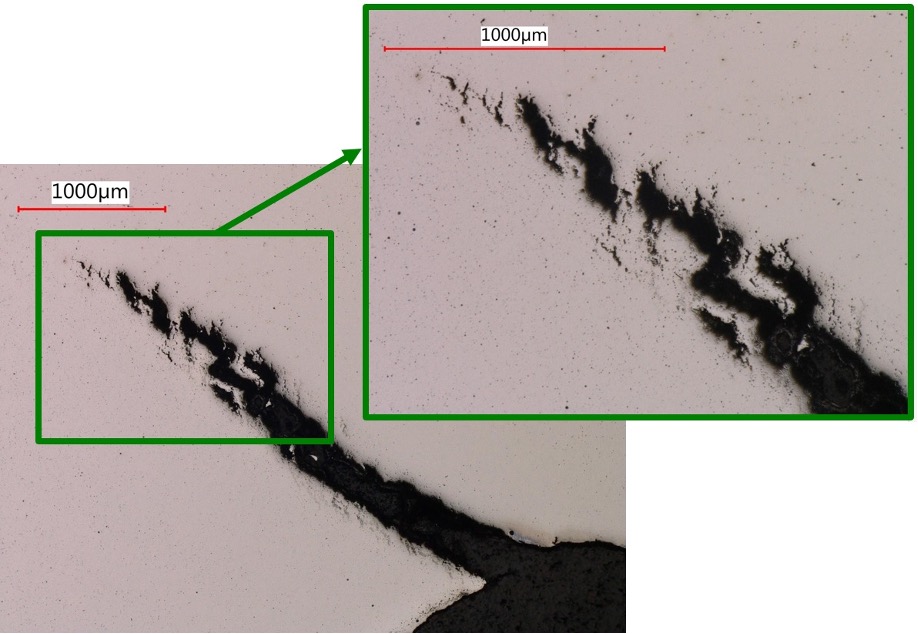
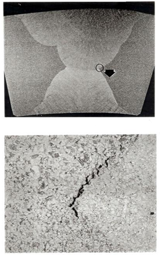
An example of a creep-related crack-like flaw occurring adjacent to the long seam weld deposit in a 36-inch catalytic reformer pipe (1-1/4 Cr – 1/2 Mo that was originally normalized and tempered after welding) is shown in Figure 6. The micro-graphs shown in this figure show a crack morphology indicative of creep voiding at the crack tip (meaning creep is the likely cause of the crack propagation through-thickness). The effects of original heat treatment on overall damage tolerance and the evolution of creep-related crack-like flaws near the weld deposit are critical factors. Other documented failures of long seam, low-chrome piping in catalytic reforming service have been documented over the years, and all these instances were due to cracks that initiated at the inside surface or embedded within the wall thickness, with no visible external damage [4-6]. An additional example of early-stage embedded creep damage in a low-chrome pipe weld is shown in Figure 7. Creep void coalescence (crack initiation) can be clearly observed at the root of the two-sided (double-V) weld. Creep cracking often propagates parallel to the weld HAZ (fusion line) as shown in Figure 7. Failure (i.e., loss of containment or rupture) will occur once the crack grows to a critical size and the remaining ligament can no longer sustain the applied loading.
Documented Industry Failures
Early industry failures of 1-1/4 Cr – 1/2 Mo components such as superheater outlet headers and piping components operating in the creep regime were attributed to weld cracking [12]. In 1968, the ASME Code reduced the (time-dependent) allowable stresses for 1-1/4 Cr – 1/2 Mo materials such that the allowable stresses at 1000°F and 1050°F were reduced by 16 and 26 percent, respectively [12]. Therefore, low-chrome headers and piping components operating in the creep regime designed during the 1950s and 1960s are potentially under-designed. A second decrease in allowable stresses prompted by industry failures took place in the 1989 addenda to the ASME Code [13], where the allowable stresses for 1-1/4 Cr – 1/2 Mo decreased from 6.9 ksi to 6.3 ksi at 1000°F and from 4.6 ksi to 4.2 ksi at 1050°F. Additionally, ASME B31.3 introduced a weld joint strength reduction factor (W) in the 2004 edition [14]. The purpose of this factor is to account for long-term behavior of welds at elevated temperatures in the absence of creep tests (above 950°F). ASME B31.1 introduced this parameter in the 2008 edition [15].
Long seam piping failures have been observed in chrome-moly welds given sub-critical PWHT as well as those that are normalized followed by tempering (N&T). The Mohave steam pipe failure (1-1/4 Cr – 1/2 Mo alloy) in 1985 and the Monroe (2-1/4 Cr – 1 Mo alloy) failure in 1986 showed direct evidence of cracking from sub-surface initiation points in regions of high stress due to local creep property mismatch and joint geometry. The cracking was preceded by creep damage in the weld HAZ or at the weld fusion line. Essentially, the effects of the different material property zones at the weld deposit led to stress intensification that accelerated the rate of creep cavity growth at the weldment. These systems operated at roughly 1000°F, and metallurgical investigations confirmed that the creep damage initiated subsurface in the long seam, and the damage significantly advanced without any apparent surface evidence on the outside diameter (OD) [16]. In addition to long-term creep damage, a major contributor to these failures included local stress increases from long seam weld peaking/misalignment. Other failures in the electric utility industry led to the development of Electric Power Research Institute (EPRI) inspection guidelines for long seam piping using ultrasonic, AE, and metallographic replication [17,18].
The Advantage of Creep Simulation Methods
Applying modern finite element analysis (FEA) techniques coupled with a continuum damage mechanics (CDM) approach makes it possible to identify the critical issues and prevent failure of pressure vessels and piping systems operating in the creep range. Furthermore, modern computational methods can help predict remaining life and help establish appropriate inspection intervals for in-service high-temperature equipment. Modern computational techniques, specifically the Omega Method [8], can be readily incorporated into FEA simulations, and as such, it represents a useful CDM approach. Commonly, the Omega Method is coupled with commercial FEA software programs through specialized user subroutines. Such subroutines can calculate time-dependent creep strain, damage accumulation, and stress relaxation throughout the model (accomplished through a viscoelastic analysis step). Accounting for stress relaxation can significantly remove conservatism relative to simply using elastic stresses to calculate creep damage. Fundamentally, creep strain rates are computed as a function of applied stress and temperature at different points in the FEA model, and composite damage is established based on user-defined (constant or variable) loading histories. Usually, non-linear elastic-plastic material properties are considered in FEA in addition to creep. This ensures that areas of elevated local stress (e.g., at welds or other complex geometric features) reasonably allow for stress redistribution and plastic strain accumulation and deformation. This type of user subroutine also permits the analyst to account for changes in the elastic modulus of the material as damage accumulates (achieved through the introduction of an elastic damage parameter). This approach produces the capability to accurately model the creep behavior of complex three-dimensional structures and welds, including capturing creep property mismatch between the weld deposit, HAZ, and adjacent base metal [4-6]. This type of advanced FEA simulation has proven that predicted creep damage evolution over time can realistically mimic actual in-service damage morphology and failures.
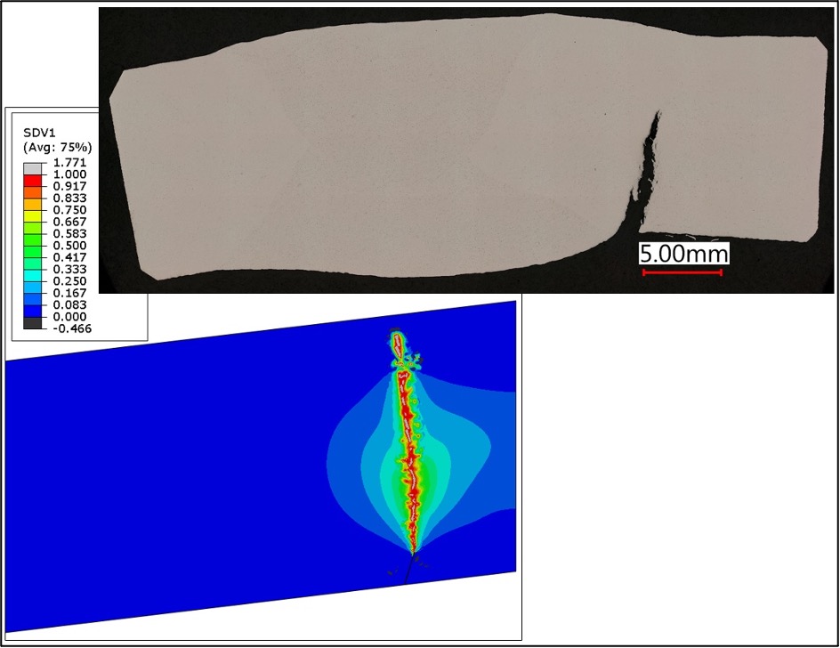
Figure 8 presents a comparison of how creep damage evolution from FEA simulations can mimic real-life crack-like flaw propagation near a weld deposit. This creep simulation reflects a normalized and tempered (N&T) 1-1/4 Cr – 1/2 Mo catalytic reformer pipe cross section with an initial 1/16-inch-deep inside surface-breaking crack-like flaw included in the base metal, directly adjacent to the HAZ. This FEA model has a local peaking magnitude of 1/8 inch and an assumed operating temperature of 950°F. In Figure 8, contours of creep damage are plotted after 12 years of operation next to a micro-graph of a creep-related crack-like flaw from a sample of an ex-service N&T catalytic reformer pipe with the same magnitude of long seam peaking. The creep damage progression observed in the sample is consistent with the FEA prediction, including the overall damage characteristics and the time for the small initial crack-like flaw to propagate to a significant through-wall size [4-6]. This analytical comparison to actual observed creep damage serves as a worthwhile validation check for the complex stress analysis approach employed. It also highlights how a computational CDM approach can result in accurate creep damage manifestation in the form of crack-like flaw growth. To this end, FEA simulations like this are valuable engineering tools that can not only accurately predict remaining life but also guide equipment inspection strategies to help owner-users manage the risk associated with creep failures at welds.
Summary and Conclusions
This article highlights the importance of understanding the high-temperature behavior of welds. The creep response of welded regions is notably complex with many factors contributing to failures including residual stresses, microstructural imperfections/defects or weak zones caused by welding, loss of optimal base metal microstructures during the weld thermal cycle, toughness changes, development of ductility lowering multiaxial stress states, and stress concentration effects due to geometrical discontinuities in the vicinity of a welded joint. It is also critical to quantify magnitude of weld misalignment (peaking) for in-service components and impose stringent tolerances on new equipment designs to maximize long-term reliability. Weld peaking can dramatically increase local bending stresses that can lead to accelerated creep damage accumulation and premature failure. Additionally, accurately predicting welded pressure equipment remaining life is valuable for components operating in the creep regime. To accomplish this and avoid significant error in test data extrapolation approaches, it is often necessary to leverage creep test data from sizeable test specimens where behavior is investigated at reasonably assigned applied stress and temperature levels (that are relatively representative of in-service operating conditions). Moreover, modern FEA-based computational techniques, in conjunction with the MPC Omega Creep Method [8], offer analysts a valuable means to utilize test data and capture the behavior of critical components (and complex geometries) operating in the creep regime. These engineering methods can lead to improved damage tolerance of new designs and help guide inspection and lifecycle management strategies for in-service equipment. The consequences of failure can be significant for high-temperature welded equipment, as highlighted by the numerous industry failures summarized herein in both the power generation and refining industries. Mitigating creep damage in welds typically requires a holistic approach that ensures favorable and technically sound design techniques, fabrication/welding practices, inspection strategies, creep testing methods, and advanced creep remaining life assessments.
References
[1] Stanford, E.G., 1949, “The Creep of Metals and Alloys,” Temple Press Limited, London, England.
[2] Prueter, P.E., “A Guide to High-Temperature Creep Management,” eBook, Inspectioneering LLC, https://inspectioneering.com/content/2023-04-13/10534/a-guide-to-high-temperature-creep-management, Spring, TX, April 13, 2023.
[3] Prager, M., Osage, D.A., and Prueter, P.E., “WRC Bulletin 560: Understanding Welds in Elevated Temperature Service,” Welding Research Council, Shaker Heights, OH, July 2022.
[4] Prueter, P.E., Dobis, J.D., Geisenhoff, M.S., and Cayard, M.S., “A Computational Study of the Creep Response of High-Temperature Low Chrome Piping with Peaked Longitudinal Weld Seams.” Proceedings of the 2016 ASME Pressure Vessels and Piping Conference, July 17-21, 2016, Vancouver, British Columbia, Canada PVP2016-63582.
[5] Prueter, P.E., Dobis, J.D., Geisenhoff, M.S., and Cayard, M.S., “Remaining Life Sensitivity to Longitudinal Weld Seam Peaking in High Temperature Low Chrome Piping,” July/August 2016 issue of Inspectioneering Journal.
[6] Prueter, P.E., “Techniques for Simulating Creep Damage Evolution at Welds with Emphasis on Evaluating Longitudinal Seam Peaking in High-Temperature Piping Systems,” ASME ETAM2018-6710, ASME Symposium on Elevated Temperature Applications of Materials for Fossil, Nuclear, and Petrochemical Industries, April 3-5, 2018, Seattle, Washington, ETAM2018-6710.
[7] Prager, M., 1995, “Development of the MPC Omega Method for Life Assessment in the Creep Range,” Journal of Pressure Vessel Technology, Vol. 117, pp. 95–103.
[8] API/ASME, 2021, “API 579-1/ASME FFS-1, Fitness-For-Service,” 4th Edition, American Petroleum Institute and American Society of Mechanical Engineers, Washington, DC/New York.
[9] Alexandrov B., Wang L., Siefert J., Tatman J., and Lippold J., “Phase Transformations in Creep Strength Enhanced Ferritic Steel Welds,” Scientific Proceedings VIII, International Congress – Machines, Technologies, Materials, Vol. 2, pp. 13-16, 2011.
[10] Brett, S. J., “Service Experience with a Retrofit Modified 9Cr (Grade 91) Steel Header,” RWE Power International. Ed. R. Viswanathan, D. Gandy, and K. Coleman. Advances in Materials Technology for Fossil Power Plants Proceedings from the Fifth International Conference. 2008.
[11] Coleman, K.K. and Newell, W.F., “P91 and Beyond – Welding the New-Generation Cr-Mo Alloys for High-Temperature Service,” Welding Journal 86(8) pp. 29-33, Aug. 2007.
[12] Nakoneczny, G. and Schultz, C., 1995. “Life Assessment of High Temperature Headers,” Presented to the American Power Conference. BR-1586.
[13] B&W, 1991. Plant Services Bulletin 1A: Creep Fatigue and Ligament Cracking of 1 1/4 Cr – 1/2 Mo-Si (T11 and P11) Pressure Parts. The Babcock and Wilcox Company, Barberton, Ohio.
[14] ASME, 2004. ASME Code for Pressure Piping: Process Piping. The American Society of Mechanical Engineers, New York.
[15] ASME, 2008. ASME Code for Pressure Piping: Power Piping. The American Society of Mechanical Engineers, New York.
[16] Lundin, C., Liu, P., Thorwald, G., and Anderson, T., 2002. Welding Research Council Bulletin 475: Studies of Local Differences in Material Creep Properties on Weldments. Welding Research Council, New York.
[17] EPRI, 1987. Guidelines for the Evaluation of Seam-Welded Steam Pipe: EPRI Report CS-4774, 1st Edition. The Electric Power Research Institute.
[18] EPRI, 2003. Guidelines for the Evaluation of Seam-Welded High Energy Piping: EPRI Report 1004329, 4 Edition. The Electric Power Research Institute.