The Hot Tapping and In-Service Welding Process
Often the most practical and economical approach to repairing a leak or installing a new nozzle is to perform welding without removing the component from service. This allows for continued operation and prevents potentially hazardous process release while safely making the modification to the component. Hot tapping itself refers to the technique of attaching a mechanical branch fitting to in-service equipment with the objective of creating an opening in that component via drilling or cutting. In most cases, hot tap procedures are followed to allow for other welding operations onto the live equipment, not only branch attachments. These operations can include external attachments, CUI restoration, flaw removal and weld build-up, etc. This article will discuss the risks involved with in-service welding, thermal analysis to quantify the risks, and practical in-service welding considerations to ensure safe and successful hot tap connections.
What Are the Risks with In-Service Welding?
When welding onto in-service equipment, there are two main concerns. First, too high of a maximum ID surface temperature during welding can result in a high risk of burn-through of the run line wall. Burn-through of the component can burst under internal pressure if there is a significant loss in the material strength, which puts the welder at risk if the contents are toxic or flammable. The risk of burn-through is considered to be high when the ID temperature is at or above 1800°F/982°C when using low-hydrogen electrodes (e.g., E7018-H4R) or 1400°F/760°C when using cellulosic electrodes (e.g., E6010). Generally, a minimum flow rate of 1.3 ft/s (39.6 cm/s) is recommended in API RP 577 [1] for pressure equipment and piping containing liquid or gas that is being hot tapped to minimize the risk of burn-through and overheating the liquids (i.e., combustion and decomposition). Thermal decomposition of the process fluid has been identified as a concern during hot tap/in-service welding operations as these create localized hot spots on the component that could contribute to burn-through. Decomposition of certain temperature-sensitive, chemically reactive materials (e.g., peroxides) or unsaturated hydrocarbons (such as ethylene) is exothermic and directly increases the ID surface temperature. As the driving force for burn-through is the heat input, API RP 2201 [2] emphasizes that minimizing the welding heat input and the use of proper weld electrode sizes are critical to avoiding overheating and burn-through.

Where,
HI = heat input [kJ/in]
V = voltage [V]
I = current [A]
S = electrode travel speed [in/min]
The other major concern with in-service welding is delayed hydrogen-induced cracking in the heat-affected zone (HAZ) of the weld. Delayed HAZ cracking is a concern in medium-to-thick-walled ferritic (typically carbon and low-alloy steels) equipment due to the ability of the large mass of material to rapidly sink heat away from the weld pool. High process flow rates and high thermal conductivity fluids (e.g., water) also directly increase the cooling rate and are a cause for concern of delayed HAZ cracking. A maximum flow rate of 4.0 ft/s (1.2 m/s) is generally recognized for liquid lines to minimize the cooling rate and risk of high hardness in the HAZ. Flow rate values are stated in [1] but are considered typical ranges or limits and not strict requirements. In ferritic materials, this cracking is associated with the diffusion and accumulation of hydrogen in the microstructure and may occur immediately following welding or after an incubation, or delay, time. The microstructure (hardness) and composition of the steel influence the susceptibility of cracking and can be used to control cracking. The carbon equivalent (CE) formulae are used to determine the net effect of composition on hardenability and predict hydrogen cracking susceptibility.

Hot Tap Thermal Analysis Overview
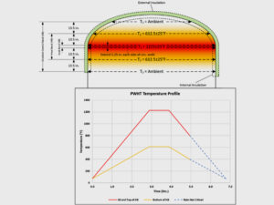
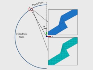
In order to quantify the risk of burn-through (or decomposition) and delayed HAZ cracking, the temperature profiles of the hot tap scenario during welding can be calculated via a numerical model. E2G’s eecHotTap application is based upon Investigation and Prediction of Cooling Rates During Pipeline Maintenance Welding [3] and is designed to accurately predict the thermal history of in-service welds and considers the effects of virtually any process fluid. Two-dimensional heat transfer analysis is solved to compute temperatures, cooling rates, and cooling times in response to heat inputs and geometry. A temperature profile is developed for each node in the finite element (FE) model (Figure 1). Once the temperature profile (i.e., temperature vs. time) is calculated, the cooling rate can be determined and used to calculate a maximum acceptable CE value based on a critical hardness. Graville and Read [4] calculated maximum hardness values as a function of the cooling rate and CE, ultimately providing an acceptable CE value for a given cooling rate based on a critical hardness for delayed HAZ cracking (shown in Figure 2). Therefore, based on the results of the thermal analysis, acceptable ranges of welding heat input (and corresponding welding variables like current, voltage, and travel speed) and process fluid flow rate can be determined for a hot tap connection to avoid burn-through or cracking.


Practical Welding Considerations for Successful Hot Taps
Successful completion of an in-service weld is generally most sensitive to the electrode velocity (rate at which the electrode will traverse a given distance) when welding. Therefore, prior to performing the hot tap installation, a mock-up weld test can familiarize the welder with the acceptable heat input and the designated travel speed. As already discussed, the welding procedure can also have a major effect on the successful completion of the weld, and restrictions are often placed on the welding process and electrode. To limit the number of possible defects, gas tungsten arc welding (GTAW) is often specified over other arc welding processes due to its high-quality, slag-free weld deposits. If using GTAW is not feasible, then shielded metal arc welding (SMAW) is often used, preferably with an electrode with a maximum diffusible hydrogen designation (per ASME II-C SFA-5.1) of H4 or lower and low-moisture-absorbing designation (R) from a hydrogen cracking standpoint. Additionally, smaller diameter electrodes are preferred to limit the heat input.
There are a number of other factors to consider prior to hot tapping, including:
- The strength of the component during welding/hot ligament under the weld pool maintaining pressure
- Effects of entrapped hydrogen in the component (hydrogen bakeout is typically not possible)
- Other potential process-side damage mechanisms like amine stress corrosion cracking (SCC) (or other residual stress-driven cracking mechanisms)
- Crevice corrosion of the hot tap connection
- Inspection considerations before and after welding
Case Study: Ammonia Line
A client approached E2G to evaluate the welding parameters for a hot tap of a carbon steel weldolet onto an API 5L (nominally carbon steel) pipeline. The typical operating conditions of this line were liquid ammonia at 70°F/21°C and 300-400 psig. The client specified that the anticipated and maximum expected flow rates of the line were 6.44 ft/s (1.96 m/s) and 9.93 ft/s (3.02 m/s), respectively, and that the CE was 0.360, as based on a laser-induced breakdown spectroscopy (LIBS) analysis.
Thermal decomposition of ammonia has been identified in some sources as a concern during in-service welding operations. ASME PVP 2017 – 65422 [5] lists ammonia as a chemical that could decompose thermally and states that decomposition is a highly temperature- and time (rate)-dependent phenomenon. Ammonia decomposition is mildly exothermic, so in some cases (such as stagnant, limited-volume vapor ammonia service, which is not the case here), once decomposition starts, it may be sustained inside the run pipe. Notably, [2] does not indicate a concern specifically for ammonia when it discusses decomposition of process fluids due to heating of welding. In order to mitigate the risk of ammonia decomposition, an active flow is required to quench the reaction and minimize the decomposition rate. While the client indicated that the hot tap would not occur during no-flow conditions, a mild risk of decomposition still remained. Due to this concern and that for elevated temperature damage mechanisms of carbon steel in ammonia-containing process environments, a reduced maximum inside wall temperature of 1200°F/648°C (from 1800°F/982°C) was assumed to define the welding heat input limits in the thermal analysis.
The risk of ammonia SCC was also considered by the analysis team for this hot tap. Ammonia SCC requires anhydrous ammonia (i.e., ammonia with less than about 0.1 wt.% water), some amount of dissolved oxygen, and high residual stress (near the yield strength of the material). Many manufacturers and users of ammonia add 0.2 wt.% minimum water content or specify post-weld heat treatment to inhibit cracking. In this case, the line contained 0.2 wt.% water minimum per supplier contract and was liquid full. This effectively removes the potential for ammonia SCC.
The thermal analysis described in this article was performed for the expected flow rates and common flow limits for information. The following conclusions and recommendations from the hot tap analysis were provided to the client:
- The proposed weldolet hot tap was predicted to be successfully welded using the heat inputs described in the table below.
| Recommended Welding Parameters for Weldolet on Ammonia Line | ||
| Flow Rate (ft/s) | Minimum Heat Input (kJ/in) | Maximum Heat Input (kJ/in) |
| 0 (no flow) | 12.5 | 22.5 |
| 1.3 | 15 | 32.5 |
| 4.0 | 17.5 | 35 |
| 6.44 | 17.5 | 50 |
| 9.93 | 17.5 | 50 |
- Any combination of welding parameters that equates to the acceptable heat input range is acceptable.
- Welding should be performed with ER70S with GTAW for the root pass and E7018-H4R with SMAW for the fill/cap passes.
- The root pass should be inspected visually and with MT before proceeding with fill passes. The final completed weld should be inspected visually and with MT after allowing the weld to cool.
- All welds should be reinspected with MT 24-48 hours after completion of welding to detect delayed hydrogen cracking.
E2G has performed thermal analysis on hundreds of components using our proprietary eecHotTap tool to provide acceptable welding parameters to avoid risks with in-service welding. If you have an in-service welding challenge and think that a detailed thermal analysis might help, reach out to our experts today.
If you have any questions for the author, please submit the form below:
References
[1] American Petroleum Institute. (2020). Welding Processes, Inspection, and Metallurgy, 3rd. Ed. (API Recommended Practice 577).
[2] American Petroleum Institute. (2020). Safe Hot Tapping Practices in the Petroleum and Petrochemical Industries, 5th Ed. (API RP 2201).
[3] Batelle Memorial Institute. (1991). Investigation and Prediction of Cooling Rates During Pipeline Maintenance Welding
[4] Graville, B., Read, J., Optimization of Fillet Weld Sizes. Welding Research Supplement: 161-169, 1974.
[5] Shargay, C., Duru, K. Hot Tapping in Oil Refineries – Corrosion and Material Concerns. (ASME PVP 2017 – 65422), 2017.