Many compressor piping vibration results from modifying a compressor system without performing adequate redesign validation steps. Modifications to reciprocating compressor piping systems usually necessitate some if not all of the original API 618 required acoustic-mechanical design assessment depending on the complexity of the type of system modifications. The objective of this article is to convey basic knowledge regarding the fundamentals of acoustic pulsation, what API 618 acoustic-mechanical analysis accomplishes, and why it is critical to perform aspects of this analysis prior to repurposing compressors or modifying compressor piping so occurrences of in-service piping vibration problems can be reduced in our industry.
Excessive pulsation-induced gas forces are responsible for the deterioration of the compressor foundations, reduction in compressor valve life, vibration fatigue damage of piping and piping components, failure of small-bore connections, and damage to supports and structural members.
API 618 Reciprocating Compressors for Petroleum, Chemical, and Gas Industry Services and API 688 Pulsation and Vibration Control in Positive Displacement Machinery Systems for Petroleum, Petrochemical, and Natural Gas Industry Services outline the minimum requirements for performing the necessary design assessments to prevent vibration-related fatigue damage to the compressor, pulsation control/suppression devices (PSDs), and attached piping network due to pulsation-induced vibration as well as other gas-related forces.
This article will provide practical guidance on which aspects of the original design analysis should be considered when modifying or repurposing an existing system and why. Let’s first address the why, and for that, let’s look at the fundamentals.
System Acoustics
When discussing potential acoustic pulsation problems with reciprocating equipment, we deliberately use the term “system.” Acoustic pulsation problems, and specifically a subset of these problems referred to as acoustic resonance, in their various forms affect the machinery, vessels, and piping and are closely connected with operating and process variables such as gas mole weight, pressure, temperature, and valve positions. The multidisciplinary assessment requires knowledge and input from typically segregated engineering disciplines such as rotating machinery engineering, structural, process, piping and fixed equipment. Adequate collaboration of these teams during an acoustic-mechanical design assessment is critical.
Acoustic resonances in piping occur because pressure pulses from the reciprocating cylinder travel at the sound speed of the gas (~1000-1500 ft/s) through the piping system and will reflect off of deadlegs, adjacent compressors, partially closed valves, or any substantial diametrical change in the piping (i.e., discharge cooler, suction scrubber or upstream separator, etc.). If the reflected portion of the wave meets the next incoming pressure pulse such that the phases of the waves add, the resulting amplitude can be magnified as much as 50x. The piping experiences unbalanced shaking forces as the area of the pipe times the peak-to-peak pressure. This mechanism is called acoustic resonance and creates the most substantial type of vibration problems in reciprocating machinery systems that can affect the compressor, piping, vessels, foundations, and supports.
The underlying physics of acoustic resonance, though complex, can be understood through a simple everyday experience: blowing over the top of an empty bottle. This action generates oscillating pressure waves at the bottle’s opening, akin to the compressor, which are significantly amplified by the bottle’s unique air-space geometry, representing the piping system. This phenomenon is known as 1/4-wave resonance. Intriguingly, adding water to the bottle shortens the air column, thereby raising the wave’s pitch or frequency – a clear demonstration of how piping length critically influences acoustic natural frequencies in compressor systems. Similarly, the 1/2-wave resonance can be experienced with a flute, where oscillating pressure waves, pleasing to the ear, are produced. The flute’s open end and the next open hole create an oscillating pressure wave, with pressure peaks and troughs (anti-nodes) at both ends.Acoustic natural frequencies for 1/4-wavelength and 1/2-wavelength resonances can be accurately predicted using the following equations for lengths of piping only containing elbows.
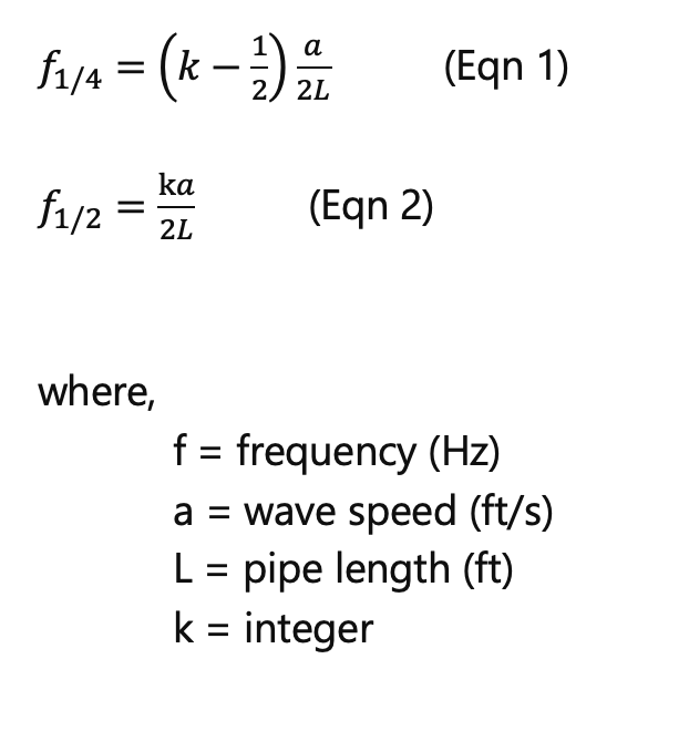
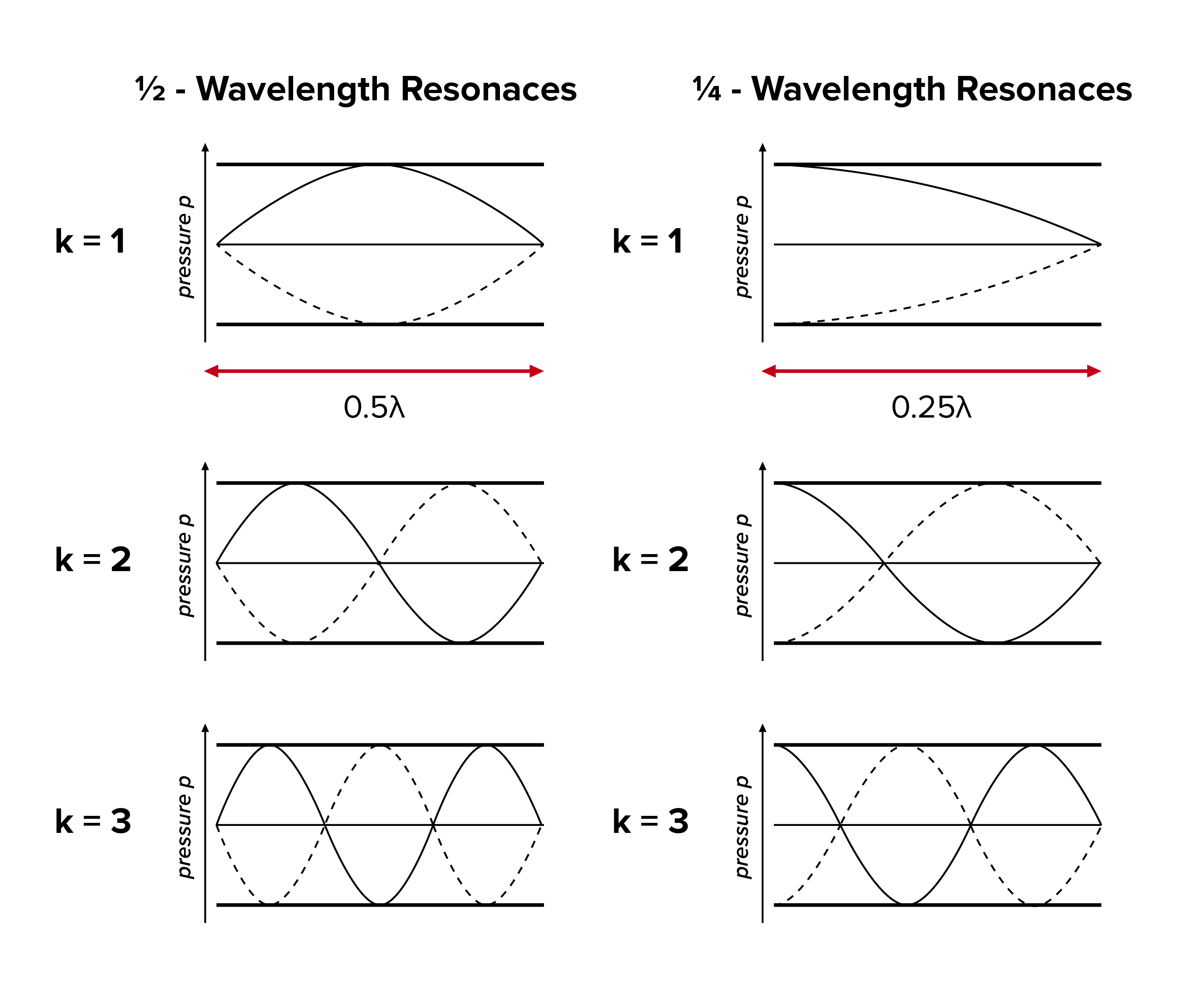
Figure 1 illustrates Equations 1 and 2 and shows the difference between dynamic pressure oscillations based on boundary conditions.
The simplified hand calculations illustrate:
- Accurate predictions can be made.
- The dominant variables are pipe length and wave speed.
- Gas composition, operating temperature, pressure, and pipe diameter come into play via the wave speed. The diameter and wall thickness affect the sound speed due to pipe wall flexibility.
Over what distance can acoustic effects occur? Does changing my piping 100 feet away from the compressor affect the system acoustics? To answer these questions, let’s rearrange Equation 2 to solve for the longest length, L, over which an acoustic standing wave equals to only one 1/2 wavelength. For typical hydrocarbons, the wave speeds can range from 1000-1500 ft/s, with hydrogen being on the lower end and methane being on the upper end of the spectrum. For a low-speed API 618 refinery machine, a running speed of 300 RPM (5 Hz) is realistic.

Clearly, system acoustic problems (i.e., resonant standing waves) can easily extend far from the machinery. Lastly, it is important to note that damping is the only attenuating mechanism that reduces the magnitudes of acoustic resonances once resonances occur. As compared to liquid systems, gases have order of magnitude less damping.
Considering the capability of acoustic waves to traverse considerable distances within piping systems, a key insight for examining piping vibration lies in understanding the relationship between the compressor and the piping. Specifically, if the frequency of observed vibration in the piping aligns with the compressor’s running speed, or an integer multiple thereof, this connection can be established. This holds true regardless of how far the site of the vibration is from the actual compressor. Such an insight is helpful in accurately diagnosing and addressing vibration issues in compressor piping systems.
System Acoustics – Computer-Based Analysis
Computer-based numerical analysis is required for predicting acoustic natural frequencies, the interaction effects between compressors and compressor cylinders, effects of control valves and orifice plates, and system pressure magnitudes, especially when considering secondary effects like fluid damping.
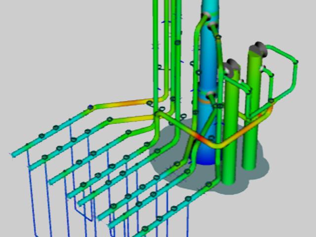
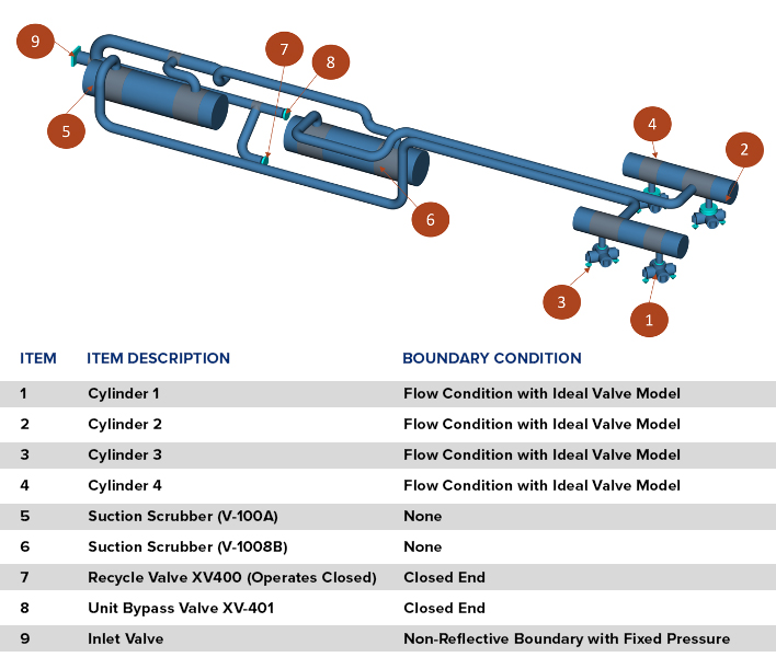
Figure 2 shows a basic acoustic model used to predict the system acoustic response on the suction side of a mid-stream, high-speed natural gas compressor unit that operates at 1500 RPM. The system is modeled from the cylinder valves to the compressor skid inlet where a non-reflective boundary condition is applied (i.e., pressure waves can exit but are not reflected back). This approach is an example of a comprehensive API 618 DA3 assessment for a new design.
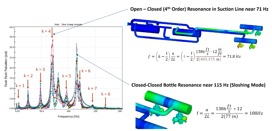
Figure 3 illustrates the pulsation solver results for a natural gas compressor design for a mid-stream client. In this figure, the numerical results for various locations in the suction line and within the suction PSD bottle are plotted as a function of excitation frequency. To produce the results, a sinusoidal excitation frequency of unit amplitude is swept through the range of frequencies presented. The figure also illustrates the accuracy and usefulness of the simplified hand calculations in predicting potential problems with this design. However, the figure just shows the acoustic natural frequencies for a unit excitation frequency swept through a wide band of frequencies, and not necessarily at the compressor excitation frequency. If the excitation is not there, the response will be zero. Therefore, the purpose is the evaluation of the interaction of the compressor excitation frequencies and the acoustic response of the piping to keep dynamic pressures below code-required limits (for on-resonance conditions) and shaking forces below code limits for instances where the piping is not mechanically resonant. This is the first major objective in performing either an API 618 DA2 or DA3 analysis, or the acoustic portion of the acoustic-mechanical analysis. Typical API 618 assessments excite a range of excitation frequencies, typically +/- 20% of the running speed(s), and ensure that the code-required limits are satisfied at harmonic multiples usually up to 10x running speed, but the largest emphasis is placed on the lower harmonics between 1x and 4x running speed where higher excitation pressures occur.
Before moving on to the discussion of mechanical behavior and its response to the acoustics, the following is a list of pulsation-related excitation mechanisms and the potential effect they can have on a system. Each of these mechanisms can be tested for and predicted in the design/re-design stage.
| Mechanism | Description | Damage/Symptom Areas |
| Non-resonant pulsation-induced shaking forces | Excessive dynamic pressures/forces in piping combined with insufficient piping support stiffnessPiping not mechanically resonant | Vibration of mainlines |
| Acoustic resonance in piping | Oscillating pressures (standing waves) in the piping that develop at the compressor running speed or one of its integer multiplesCan occur over very long distances (hundreds of feet) away from the compressor | Vibration of mainlinesVibration/fatigue small-bore connectionsDamage to supports/structures |
| Acoustic pulsation or excessive non-resonant shaking force within suction and discharge bottles (pulsation suppression devices or PSDs) | Oscillating pressures (standing waves) in the PSD chambers at the compressor running speed or one of its integer multiplesVibration typically closer to the machine | Fatigue cracks in bottle nozzle and cylinder flange weldsFatigue cracking of bottle internalsIncreased compressor vibrationFoundation damage |
| Compressor cylinder flange pulsation | Oscillating pressures (standing waves) that develop between the PSD bottles and the cylinder gas passages | Increased compressor vibrationFoundation damage |
| Cylinder gas passage shaking force | High-frequency oscillating pressures (standing waves) within the cylinder gas passages | Chattering and reduced valve life |
Mechanical Response
The second major aspect of an API 618 computational acoustic-mechanical analysis is the mechanical portion. Many engineers are at least somewhat familiar with the concept of mechanical natural frequencies and that good engineering design will ensure that the mechanical natural frequencies of the piping/vessel/structure have sufficient separation margin (typically 20% is standard) from a known excitation frequency. The same can be said for the acoustic natural frequencies in the process gas and the known excitation frequencies from the pistons. The complexity of the mechanical analysis portion of an acoustic-mechanical analysis is what distinguishes between DA2 and DA3.
Predicting the future occurrence of vibrations in compressor systems – including the frame, cylinders, PSD bottles, and piping – hinges on the accurate calculation of mechanical natural frequencies. One of the primary sources of error in this prediction is using finite element analysis (FEA)-based methods that oversimplify model boundary conditions. Common oversights include assuming that piping supports are completely rigid, that suction knock-out drums or separators are firmly attached to their bases, or that the compressor crankcase is mounted on an immovable foundation. Such assumptions, explicitly cautioned against in API 618, lead to significant errors in vibration prediction. This scenario exemplifies the principle of “garbage-in, garbage-out,” emphasizing the importance of realistic assumptions in modeling for accurate outcomes.
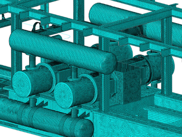
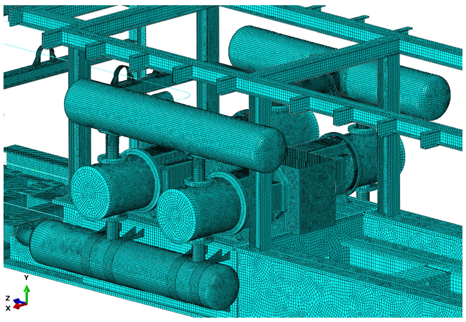
Figure 4 and Figure 5 show the cross section of the same compressor case and the associated FEA mesh discussed in Figure 2. These figures illustrate the typical model complexity required for predicting accurate mechanical responses of compressor PSD bottles and compressor cylinder heads due to the stiffness or lack of stiffness in the compressor crankcase and foundation. In this example, the suction PSD bottles are supported at their nozzle necks on structural steel that also supports the piping and is mounted to the compressor skid. Therefore, a single model to predict the shared response of the entire structure is necessary.
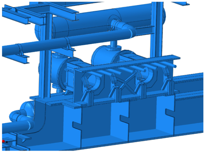
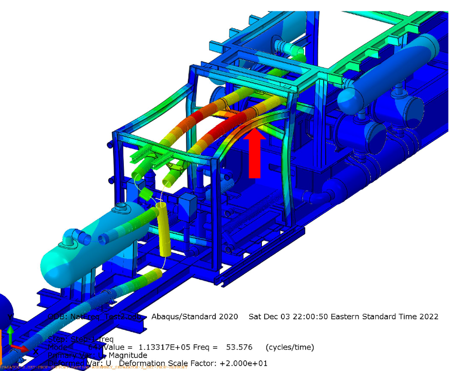
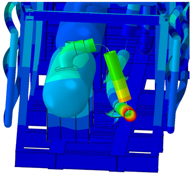
Using this model, mechanical natural frequencies were identified in the suction piping within 7% of 2x the compressor running speed, which was a frequency with substantial excitation energy (see Figure 6 and Figure 7). Support modifications were made to stiffen this frequency above 2.4x the running speed, and the compressor has experienced successful operation over the past year. Additionally, Figure 7 shows the importance of the detailed modeling of the suction scrubber vessel and piping support nearest the scrubber to accurately identify this potentially problematic natural frequency. If the support or the vessel nozzle was assumed rigid, the predicted natural frequency would be extremely inaccurate.
The question of the required separation margin in these systems is important. Can we realistically achieve it every time? In complex systems like these, we often find many mechanical natural frequencies that fall within 20% of a certain running speed. According to Section 7 of API 618 5th Edition, there should be a 20% separation margin between these frequencies and any excitation frequencies that have significant energy. This requirement, which can be somewhat unclear, typically calls for expert judgment or the use of a forced response analysis. This analysis involves applying the shaking forces, as determined by the acoustic model, to the mechanical FEA model to assess how severe the vibrations might be.
Why the common rule-of-thumb 20% separation margin? A 20% separation margin is to ensure a true 10% separation margin by accounting for an additional 10% in modeling errors. Therefore, when performing simple design changes or piping modifications for existing systems, experimental field testing/measurement of the mechanical natural frequencies via impact testing or experimental modal analysis is more accurate and leads to less identification of false positives when compared to detailed FEA modeling that may flag more problems and lead to more design iterations. The experimental field-based approach to piping modifications can be more cost-effective if paired with simplified calculations and field adjustments/additions of supports if mechanical natural frequencies are identified within the more narrow 10% separation margin. Start-up testing of the machinery and piping is always advised even if API 618 design analysis is used.
Modifications to piping supports, such as adding braces or gussets to small-bore cantilevered connections, carry the risk of inadvertently negatively altering the mechanical natural frequency. This alteration can shift the mechanical natural frequency, potentially bringing it within 10% of a higher-order running speed harmonic. Such a shift might introduce new vibration issues that did not exist before. This phenomenon is often colloquially described as “bracing the vibration here only to transfer it elsewhere.” While not technically accurate, this saying captures the unintended consequences that can arise from seemingly minor adjustments to the piping supports.
Vibration failures of small-bore piping on reciprocating compressor systems are clearly the most common type of failure that occurs in our industry. E2G has years of experience evaluating and surveying small-bore cantilevered connections and failures. Even for low-speed reciprocating compressors, we have found small 10-inch-long cantilevered connections excited by very high orders of running speed, i.e., 13x running speed. Clearly, assuming the excitation occurs only at low orders of running speed is not accurate. Given the complexity of including these small connections into mechanical FEA models as the ones shared above, the connections are typically omitted. Practically, small-bore connections are best managed using adequate design practices and field-testing following commissioning or following any modification of the small-bore connections. Not including small-bore connections in the design assessment, lack of good engineering standards for their design, and lack of inspection practices involving vibration are the reason for small-bore connections failures in our industry.
Summary of API 618 Design Approaches
Now that we have covered the basics of acoustic and mechanical design, the API 618 design approaches are reviewed here.
The acoustic-mechanical analysis has three levels of complexity called design approaches (DA1, DA2, and DA3). DA1 uses hand calculations that are often used by equipment packagers to initially size the compressor suction and discharge PSDs. Alternatively, this approach is only used on low pressure-low HP systems. DA2 and DA3 require specialist engineering firms familiar with compressor and piping acoustics, mechanical compressor and piping design, process design, and structural design to make adequate predictions of how the system will behave prior to its commissioning.
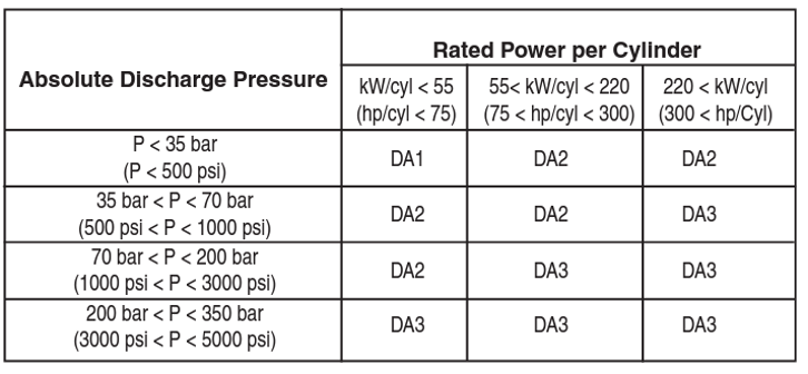
Table 2 below (taken from API 618 5th Edition) differentiates the requirement for each design level based on the compressor’s absolute discharge pressure and the rated power per cylinder.
DA2 focuses on acoustic simulation coupled with a mechanical review of the piping restraint system. It involves using pulsation suppression devices, such as dampeners, and sound engineering practices to control the vibrational response of the piping system. This approach evaluates the interaction between the compressor and suppression devices, considering the effects on compressor performance and the evaluation of shaking forces within the suppression devices. The evaluation stops short of a full mechanical analysis of the piping system. Instead, the mechanical response of the piping is handled via the use of maximum piping span tables and more simplified hand-based calculations to ensure an adequate separation margin between excitation and natural frequencies.
In contrast, DA3 includes all the elements of DA2 but adds a comprehensive mechanical analysis of the compressor cylinder, suppression devices, and associated piping systems. It looks at the interaction between acoustic and mechanical responses, including the forced mechanical response when necessary. DA3 aims to predict mechanical natural frequencies and ensure they are designed to meet specific separation margin criteria, and ensure shaking forces do not exceed set limits. This approach starts at a rigid point in the compressor system and includes analysis up to the second rigid pipe clamp on the suction and discharge piping away from the pulsation suppression devices.
DA3 is more thorough than DA2 because it not only considers the acoustic behavior of the system but also integrates a mechanical perspective to avoid resonances that could amplify shaking forces. It includes the evaluation of cyclic stresses in the compressor components based on their flexibility and dynamic movements, and it takes into account the allowable vibration limits for components.
Recommendations When Repurposing or Modifying Systems
For evaluating excessive vibration in existing in-service machinery and piping systems or when modifications are made to existing compressor systems, several aspects of API 618 and API 688 should be leveraged to ensure that modifications do not alter the system acoustics, creating excessive piping vibration. As part of any revamp or alteration project, E2G recommends an initial risk assessment of the project to identify which aspects of the system could be affected (either acoustically or mechanically, or both). The outcome of this risk assessment will identify which aspects of the API 618 acoustic-mechanical analysis should be performed as part of the modification or repurposing.
- Computational Acoustic Pulsation Analysis (Per DA2 and DA3):
- Used when the lineal feet of the process-wetted piping are altered from their original as-designed condition.
- Recommended full DA3 analysis (acoustic and mechanical) when repurposing compressors for different services.
- Not required when mechanical only changes are made, i.e., modified piping support(s).
- Does not need to be performed for alteration of small-bore branch piping less than NPS 2.
- Modifying an old compressor piping system and missing drawings? Do the suction and discharge PSD bottles have internals? Either radiography or visual inspection of the PSDs is an option, or a comparative analysis of the before and after system can be performed by making the assumption that no bottle internals exist (volume-only bottles).
- Because the important dimensional variables of the compressor gas passages are not likely available for in-service machines, modifications to piping lengths do not require detailed analysis of high-frequency, short-wavelength, gas-passage dynamics because the compressor is unchanged. Therefore, more simplified acoustic boundary conditions can be assumed on the compressor cylinder heads.
- Can omit cylinder gas passage and valve dynamics, cylinder flange pressure pulsation and shaking force checks, and PSD shaking force checks when only making modifications to the piping.
- Areas especially sensitive to piping modifications are the inlets of pressure relief piping, addition of bypass or recirculation piping, modification of the size of the suction scrubber or separator vessels, rerating of compressor cylinders to increase capacity, and addition of valve unloaders to add capacity control. The objective is to ensure that the modified piping does not create acoustic standing waves (acoustic resonances) that did not previously exist in the original system.
- DA3 Mechanical Analysis:
- Recommended following computational acoustic analysis for any alteration or modification to mainline piping or service conditions.
- Recommended for alteration or modification to piping supports only unless a pre-start-up field testing of the mechanical natural frequencies is not performed. Pre-start-up field testing of the mechanical natural frequencies and use of a less conservative 10% separation margin (because the natural frequency is directly measured and not predicted) followed by an in-service vibration assessment at all operating conditions is recommended.
- Can usually omit forced response analysis when coupling separation margin analysis with pre-start-up field testing and potential in-field piping support modifications.
- Simple Mechanical Design Review:
- Often sufficient for modification to any small-bore cantilevered connections (i.e., vents, drains, pressure or temperature gauges, etc.) or auxiliary piping systems (i.e., coolant lines, fuel gas lines, lube oil systems, etc.).
- However, due to the risk of creating new resonance conditions at higher frequencies when adding supports, an in-service field inspection for abnormal vibration is always advised.
- Static Pipe Stress Analysis for Compliance to ASME B31:
- The necessity of this analysis increases when operating temperatures exceed 200°F.
- Recommended when interstage or discharge coolers are mounted off-skid.
- Recommend including nozzle loads on separation or scrubber vessels, exchangers, or cooler header-boxes if major piping reroutes take place.
- Torsional Vibration Analysis:
- While not the focus of this article, any modification that includes changing of the driver (motor to engine, etc.) or modification of the operating conditions or service should include an updated torsional vibration analysis of the compressor and driver system.
- Field Analysis:
- Recommended as the starting point if a prior modification or equipment repurposing has led to a new systemic vibration problem with the compressor and/or piping.
- High-speed pressure testing using special field testing equipment at the compressor cylinders and at available vent, drain, or pressure taps is a valuable approach and produces useful data for acoustic model validation of existing systems that are currently problematic.
- Valid approach when making modifications to small-bore connections.
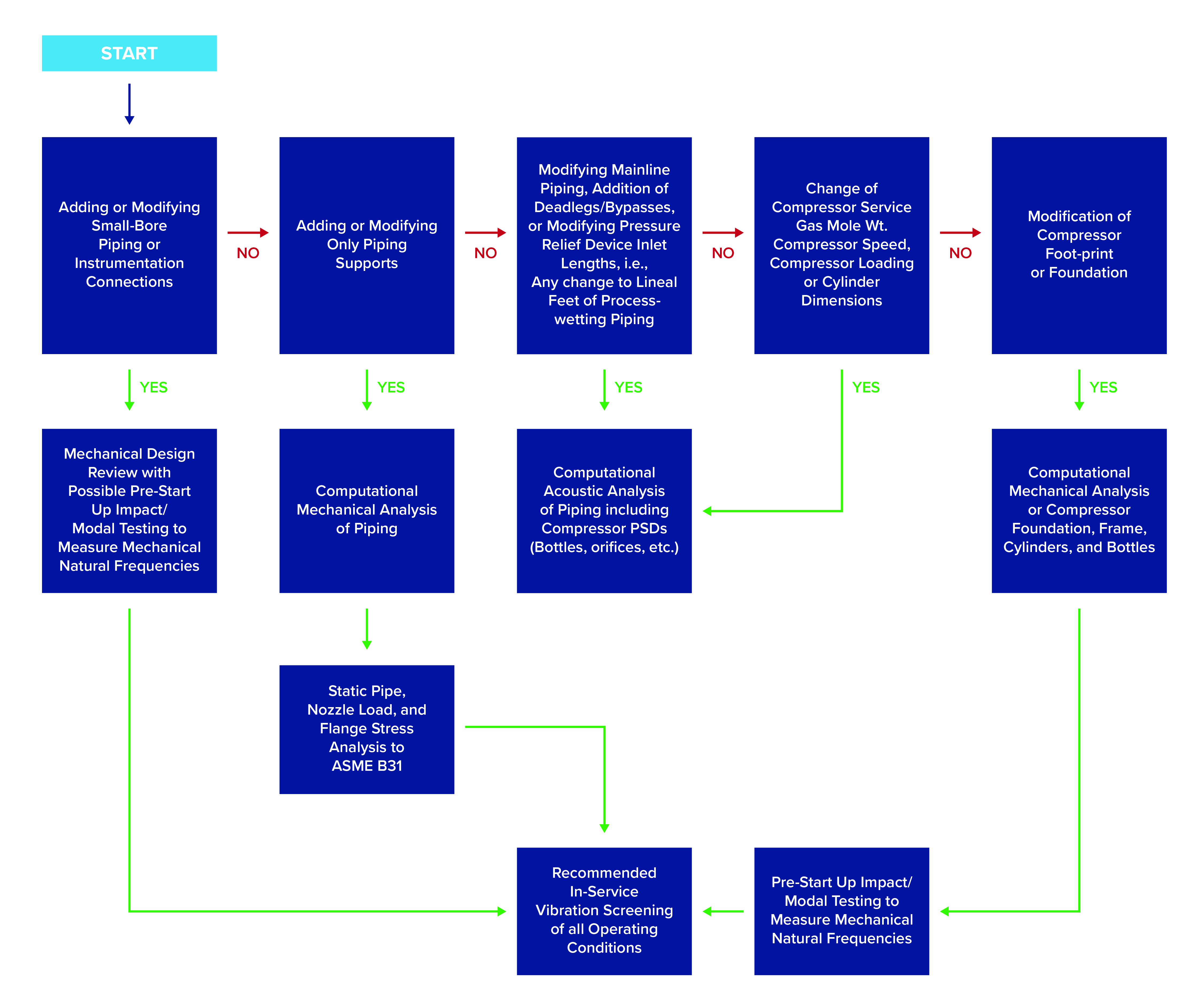
A decision-making flow diagram is provided in Figure 8 to help you make appropriate decisions when modifying or repurposing your equipment.
In summary, adhering to certain aspects of API 618 and API 688 is crucial when modifying reciprocating compressors and piping systems. These standards provide a comprehensive approach to managing the complexities of acoustic pulsation and vibration. By following these guidelines, organizations can ensure the safety, efficiency, and longevity of their compressor systems, maintaining optimal performance and reliability.