Introduction
Flow meters are critical components of petrochemical plants, as they enhance operational efficiency, safety, and regulatory compliance. Flow meters play a key role in measuring the rate of fluid movement within the complex network of process pipelines, and they act as eyes and ears of a petrochemical plant. They provide real-time insights into the movement of liquids and gases through the pipelines. Flow meters also enable precise monitoring of flow rates, allowing for efficient resource management. They contribute to sustainable practices by minimizing waste and energy consumption. Additionally, flow meters play an important role in maintaining safe operations by providing accurate data on fluid movements, helping in the prevention of leaks, spills, and other potential hazards. Accurate flow measurements allow plant operators to fine-tune processes, ensuring optimal production rates and minimizing inefficiencies. In the scenarios involving the transfer of fluids between different entities, accuracy in measurement is essential for fiscal accountability. Flow meters ensure fair and transparent transactions during custody transfers, contributing to financial integrity and industry trust. Advanced flow meters supplied with diagnostic capabilities offer monitoring of critical parameters. Early detection of irregularities in flow patterns allows for prompt intervention, preventing equipment failures and minimizing production downtime. The data provided by flow meters helps in making informed decisions, optimizing processes, and identifying areas for continuous improvement.
Types of Flow Meters
Flow meters can be divided into three different types: differential pressure (DP) flow meters, volumetric flow meters, and mass flow meters. DP flow meters include orifice plates, Venturi tubes, averaging pitot tubes, wedge meters, cone meters, flow nozzles, etc. Volumetric meters are comprised of vortex, magnetic, turbine, positive displacement, and ultrasonic meters. Mass flow meters are Coriolis and thermal meters. This article discusses working principle, uncertainty, turndown ratio, installation, advantages, and limitations of DP flow meters. Other types of flow meters will be discussed in future articles.
Working Principle:
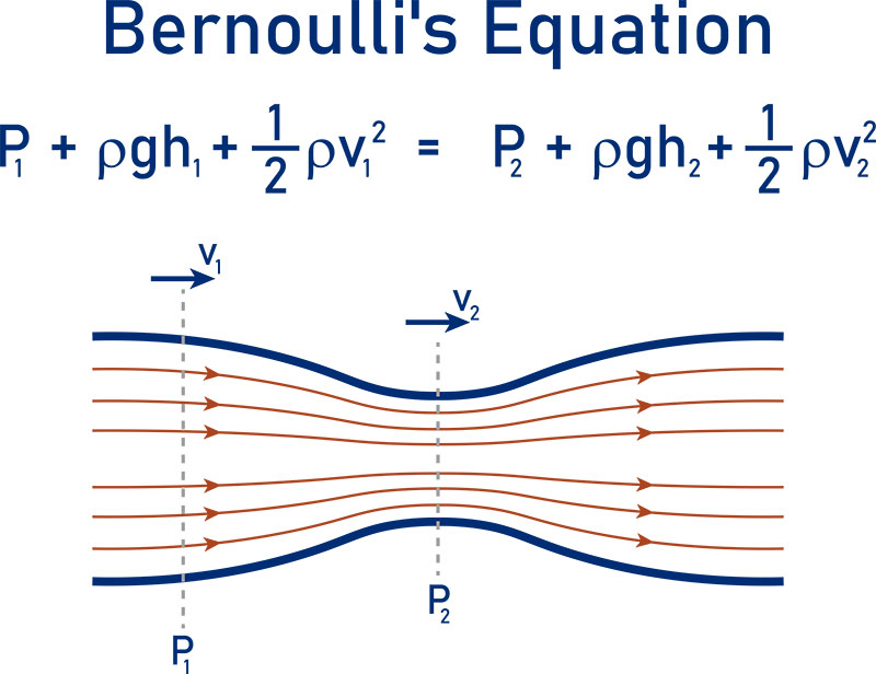
Flow measurement is an important aspect of managing processes in a petrochemical plant, and one of the most commonly used technologies is the DP flow meter. DP flow measurement has maintained its popularity and reputation as a reliable technology for more than a century. DP flow meters are based on Bernoulli’s equation, which states that the sum of all energy in the fluid flow—both kinetic energy and potential energy—remains constant regardless of conditions.
DP flow measurement involves two key components: the primary element, which is installed in the pipe; and the secondary element, transmitter. DP generated by the DP flow primary element is read by mechanical gauges or DP transmitters that convert the mechanical pressure signal into an electrical signal (analog or digital) and send it to the plant process control system (PCS) or safety instrumented system (SIS). The pressure differential, caused by a constriction in the flow path, is measured between the upstream (high) side and downstream (low) side of the DP flow primary element. The flow is proportional to the square root of the resulting DP provided density remains constant. The general form of equation for a DP flow meter is expressed as:

Where:
- Q is the volumetric flow rate (measured in cubic meters per second or other volumetric units).
- Cd is the discharge coefficient.
- A is the cross-sectional area of the pipe through which the fluid flows.
- ΔP is the differential pressure across the restriction in the flow path.
- ρ is the density of the fluid.
Different types of DP flow meters may have some variation of the above equation depending on design and characteristics. This fundamental concept forms the basis for several types of DP flow meters, each designed for installation in specific applications.
Orifice Plates
Orifice plates are the simplest type of DP flow primary element. Typically, they are fabricated using 316SS. Other non-standard materials such as Hastelloy, Monel, and duplex SS can be used for orifice plate fabrication. Factory calibration is not needed for orifice plates before installation.
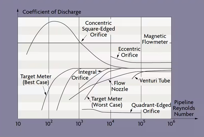
Square edge concentric orifice plates are sized as per ISO 5167-2 or ASME MFC-3M. They are recommended to be used in clean gas and liquid service. It is also recommended to use them where the Reynolds number is over 4000. The uncertainty for concentric square-edge orifice plates is superior to other DP flow meters. Eccentric or segmental orifice plates are sized as per ISO/TR15377. They are recommended to be used in 2-phase and dirty gas or liquid service.

Figure 2: Cross-section – Square edge orifice plates [2]


Quarter circle and conical entrance orifice plates are sized as per ISO/TR15377. They are used in services where the Reynolds number is ≤4000 for viscous liquids.
For liquids with entrained gas or vapor, a vent hole in the plate can be used in a horizontal meter run to prevent accumulation of gas ahead of orifice plate. In dirty service, vent holes should not be used as they may result in plugging. Similarly, a drain hole in the plate can be used for gas with entrained liquid in a horizontal meter run. Orifice plates in services with gas entrained in liquid or liquid entrained with gas shall preferably be installed vertically to allow the liquid or gas to move through the plate and not accumulate on the upstream side. Orifice plate flow meters are used to measure the flow in both liquid and gas services including viscous and corrosive fluids. Density is required to calculate mass flow rate or volumetric flow rate. In order to reduce errors due to variation in density, pressure-temperature compensation can be applied to calculate real time density, particularly in gas service.
Accuracy: The uncertainty associated with the discharge coefficient of a sharp-edge orifice plate is dependent on the β ratio and the Reynolds number. For Re ≥108 and β between 0.2 and 0.6, the maximum uncertainty is 0.5 % [3].
(0.7 – β)% for 0.1 ≤ β < 0.2;
0.5% for 0.2 ≤ β ≤ 0.6;
(1.667β – 0.5)% for 0.6 < β ≤ 0.75.
Conical entrance, quarter circle, and eccentric orifice plate have a 2% uncertainty.
Turndown Ratio: As orifice plate meters have a square root relationship between the DP-generated and the flow rate, the turndown is limited to 3:1. Multiple transmitters installed in parallel configuration can be used to achieve greater turndown.
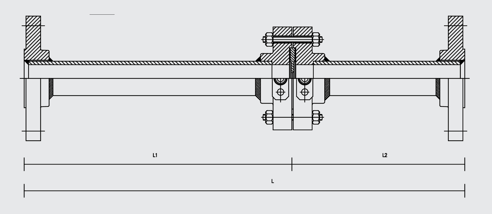
Installation: The orifice plate is installed between a pair of flanges. To avoid errors resulting from disruptions of the flow pattern due to pipe bends, valves, fittings, etc., a straight run of upstream and downstream pipe is required to develop a uniform profile. MFC-3M-2004, Table 2-3 and ISO 5167-2-2003 Table 3 provide straight run lengths for β ≥ 0.20 to 0.75 with various piping configurations.
Advantages:
- Simple design with no moving parts means easy fabrication and installation and lowers the likelihood of mechanical failures
- Cost-effective compared to other flow meters
- Can be used for a wide range of applications including liquids, gases, steam, and dirty services
Limitations:
- Potential to cause significant permanent pressure loss in large flow applications that can affect overall system design
- Measurement is highly sensitive to installation conditions
- Limited turndown ratio compared to other flow meter technologies
- May experience erosion or corrosion over time in applications where the fluid contains abrasive particles or is corrosive
- Sensitivity to variations in density of the fluid being measured; changes in density impact the accuracy of the flow measurement, and compensation is required to reduce errors
Integral Orifices
Integral orifice meter run is an assembly. It is designed for smaller line sizes of less than 2 inches where the piping surface geometrical imperfections have an effect on the measurement. It is a suitable measurement for gases and liquids including viscous fluids, fluids with suspended solids, or fluids with gas entrainment. It is designed according to ASME MFC-14M-2003 [5]. The piping and flanges are fabricated as per piping specification appropriate for the service, and orifice plate is fabricated in 316SS.
Accuracy: Integral orifice meter run has a 1% uncertainty.
Turndown Ratio: Similar to an orifice plate, integral orifice plate meter has a square root relationship between the DP generated and the flow rate; thus the turndown is limited to 3:1.
Installation: Integral orifice assembly includes calibrated upstream and downstream pipes. Upstream and downstream straight lengths vary for each manufacturer. Because an integral orifice is fabricated as one unit, there is a reduction in inaccuracies.
Advantages:
- Solution for measuring a wide variety of fluids in small pipes using conventional orifice plate
- Suitable for liquid and gas flow measurement
Limitations:
- Significant permanent pressure loss in large flow applications and can affect overall system design
- May experience erosion or corrosion over time in applications where the fluid contains abrasive particles or is corrosive
- Sensitivity to variations in density of the fluid being measured; changes in density impact the accuracy of the flow measurement, and compensation is required to reduce errors
Venturi Tubes
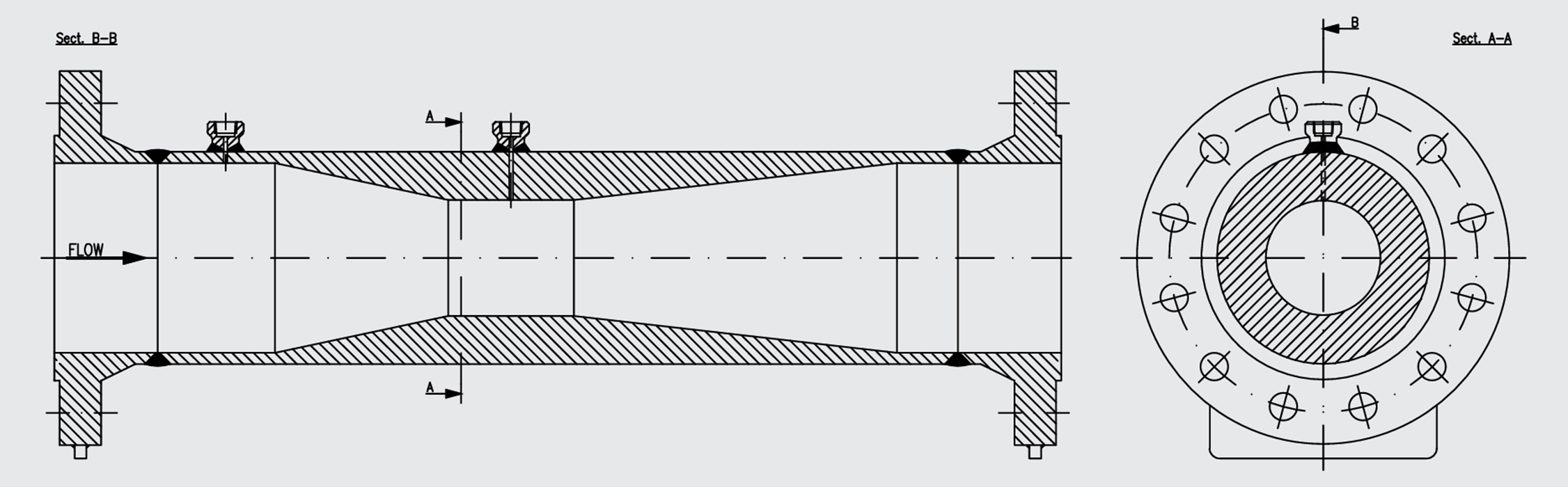
The classic Venturi tube is the most commonly used flow tube. It was designed by Clemens Herschel in 1887. It consists of a cylindrical inlet section equal to the pipe diameter, a converging section where fluid velocity increases due to decrease in cross cross-sectional a cylindrical throat section where fluid velocity remains constant, and a divergent section where velocity decreases and almost all the pressure is recovered. The lay length can be shorted by using a 15° outlet divergent with a truncated outlet. However, this can cause some permanent pressure loss.
Cast Venturi tubes are made from cast iron. Fabricated Venturi tubes are made from carbon steel, stainless steel, and other alloys. The throat section is usually stainless steel to avoid erosion due to high velocity. Separate pairs of taps are provided for redundant flow measurements. The classic Venturi tube is sized as per ASME MFC-3M and ISO 5167-4 [5, 10]. Similar to an orifice plate flow meter, density is required to calculate mass flow rate or volumetric flow rate. In order to reduce errors due to variation in density, pressure-temperature compensation can be applied to calculate real time density, particularly in gas service.
Accuracy: As per API 551 Figure 20, the Venturi cast with throat and entrance cylinder machined can achieve uncertainty of 0.7%. The Venturi cast with throat, conical convert, and entrance cylinder machined can achieve uncertainty of 1.0%. Similarly, the Venturi manufactured by welding sheet iron can achieve uncertainty of 1.5% [3].
Turndown Ratio: As Venturi meters have a square root relationship between the DP generated and the flow rate, the turndown is limited to 3:1. Multiple transmitters installed in parallel configuration can be used to achieve greater turndown.
Installation: The Venturi tube can be installed in any position to suit the requirements of piping. To avoid errors resulting from disruptions of the flow pattern due to pipe bends, valves, fittings, etc., a straight run of upstream and downstream pipe is required to develop a uniform profile. ISO 5167-4-2003 Table 1 provides straight run lengths for β ≤ 0.30 to 0.75 with various piping configurations [10].
Advantages:
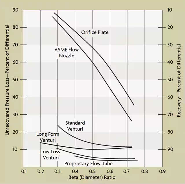
- Cause low permanent pressure loss – see below comparison
- Can be used for a wide range of applications including liquids, gases, steam, and dirty services
Limitations:
- More expensive to manufacture and install compared to orifice plates
- Limited turndown ratio compared to other flow meter technologies
- Sensitivity to variations in density of the fluid being measured; changes in density impact the accuracy of the flow measurement, and compensation is required to reduce errors
Averaging Pitot Tubes
Pitot tubes were invented by the French engineer Henri Pitot in 1732 to measure the flowing velocity of fluids. Pitot tubes are used where minimum pressure drop is needed. A traditional pitot tube consists of a slender tube inserted into a flowing fluid. It measures two pressures: the static pressure and the total pressure. The static pressure is the operating pressure, measured upstream to the pitot tube. It is measured at right angles to the flow direction, preferably in a less turbulent section. The difference between total pressure and static pressure is measured using a transmitter, and then it is converted into a flow rate.
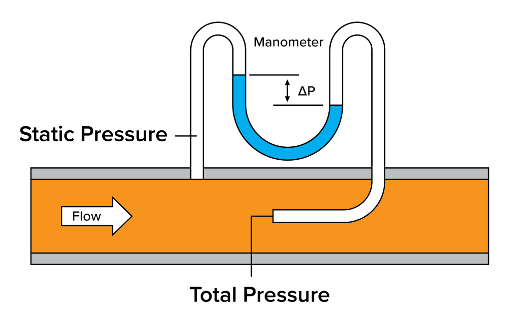
Insertion of two tubes into a pipe may not be practical and can be expensive. Hence, the hole measuring the total pressure and the holes measuring the reference or static pressure are incorporated into the same device.
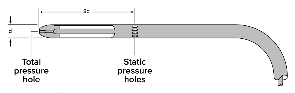
Pitot tubes sample a single point. As the flow profile of the fluid changes across the pipe diameter, the accurate placement of the nozzle is important. To avoid this problem, averaging pitot tubes are used. In other words, averaging pitot tubes take the pitot tube concept further by incorporating multiple pressure-sensing ports around the tube circumference. These ports are strategically positioned to sample the pressure at various points across the pipe diameter.


Figure 12: Averaging pitot tube installation methods [14]
By measuring pressure at multiple points, averaging pitot tubes provide an average velocity measurement across the entire cross-section of the pipe. This averaging helps compensate for irregularities in the flow profile, making them suitable for applications where flow conditions may be non-uniform. Averaging pitot tubes can be fabricated from corrosion-resistant materials such as 316SS. Pitot tubes and averaging pitot tubes are appropriate for the measurement of single-phase media, which completely fill the cross-section of the pipe. Since the primary element is installed within the fluid stream, each application should be designed to withstand the bending moment and vortex shedding harmonics.
Accuracy: Uncalibrated uncertainty typically is 1.0% for liquids and 1.5% for gas – but with calibration, 0.5% uncertainty is achievable.
Installation:
- If the natural frequency of the averaging pitot tubes coincides with the vortex shedding frequency, an end support can be welded on the opposite side of the pipe.
- Averaging pitot tubes can be installed while the plant is in operation. They can be mounted 2D from an elbow, but prior to the elbow, additional straight run is required.
Advantages:
- Causes no pressure loss in the flowing fluid
- Cheap and very easy to install
Limitations:
- Difficult to obtain proper alignment with flowing direction
- Cannot be used in fluids with suspended solids and impurities
- They require a turbulent flow profile. The fluid velocity should be high in order to get a measurable pressure difference.
- Turndown is limited to approximately 3:1 by the square root relationship between pressure and flow.
Wedge Meters
The wedge meter has a V-shaped block. When the fluid is passing over the V block, the flow area reduces, the flow velocity increases, and the static pressure is reduced. This causes the static pressure difference across the wedge. The square root of pressure difference is directly proportional with the flow rate. It is designed as per ISO 5167 part 6 [15].
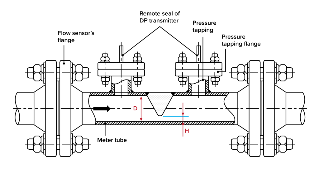
H is the height of the opening below the restriction. D is the internal diameter of the pipe. The ratio H/D is critical to calibrate the meter as H has custom dimensions. The wedge meter design is suitable for Reynolds numbers ≥500. The wedge meter is available in any pipe size, but its use is limited to challenging fluids. They are available in carbon steel, low-temperature carbon steel, 316SS, and special alloys such as Hastelloy C276, Inconel 625, Monel 400, duplex, super duplex, etc. The wedge meter can measure flow bi-directionally. It is designed to use for all types of flow, especially for highly viscous, dirty, abrasive, slurry, or muddy media. Pressure-temperature compensation is required due to density variation.
Accuracy: A calibrated wedge meter can have 0.5% uncertainty. An uncalibrated wedge meter can have an uncertainty of 5%. Uncertainty varies based on H/D ratio. See the table below.

Installation: The wedge flow meter can be installed vertically or horizontally. Minimum upstream and downstream lengths are dependent on the type of fittings at the end of the straight run and pipe configuration. Minimum straight lengths of 10D upstream and 5D downstream are recommended with one piping elbow configuration upstream of the wedge meter.
- Permanent pressure loss lower than that of orifice plate
- No moving parts and robust design; hence, low maintenance is required
- Designed for dirty, abrasive, slurry, or muddy fluid
- For very high and very low Reynolds numbers
- Unaffected by velocity profile distortion
- Turndown typically >10:1, depending on transmitter configuration
Cone Meters
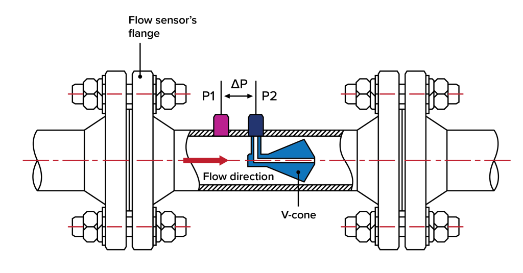
A cone meter is an engineered flow element. It is pre-assembled with a cone welded in a pipe spool piece. Cone meters are designed as per ISO 5167-5. The sensing taps are 1⁄2-inch or 3⁄4-inch. They can be butt- or socket-weld, threaded, or flange connections. The taps can be installed with isolation valves. The DP changes based on flow rate changes.
They are fabricated in 316SS, carbon steels, and other special alloys such as Hastelloy C276, Inconel 625, Monel 400, duplex, super duplex, etc.
Accuracy: The cone meter has uncertainty of up to 0.5% of the rate when calibrated properly.
Installation: For the best performance, depending on fittings or valves in the pipeline, a cone meter needs 0D to 5D upstream straight run and 0D to 3D downstream straight run. Due to the shortest upstream and downstream straight length requirements, a cone meter can be easily retrofitted into existing piping.
- Turndown is 10:1 and can measure the flow with a lower Reynolds number
- Produces small swirls that lead to a low-amplitude signal and high frequency, reducing signal noise as compared to an orifice plate.
- As per API RP 551, no longer patent protected, and there are a limited number of suppliers
Conclusion
Selecting the right DP flow meter is a crucial decision that directly impacts the efficiency and accuracy of fluid flow measurements. By carefully considering factors such as flow characteristics, pipe size, turndown, accuracy requirements, installation constraints, and maintenance needs, users can make informed decisions that align with their specific application demands. E2G can help select the right DP flow meter technology for your plant. Appropriate DP flow meter selection will enhance process control, improve energy efficiency, and ensure the overall hydraulic balance of the system.
Click here to download Table 2: DP Flow meter Comparison Table. [19]
Find more information here, and use the form below to submit questions for the author:
- https://www.shutterstock.com/image-vector/bernoullis-principle-equation-fluid-flow-physics-2221083847
- https://www.wika.com/media/Data-sheets/Flow/Primary-flow-elements/ds_fl1001_en_co.pdf
- Process Measurement - API Recommended Practice 551 Second Edition, February 2016
- https://www.omega.com/en-us/resources/orifice-plate-flow-meter
- ASME-MFC-3M – 2004 - Measurement of Fluid Flow in Pipes Using Orifice, Nozzle, and Venturi
- ISO 5167-2-2022 - Measurement of fluid flow by means of pressure differential devices inserted in circular cross-section conduits running full - Part 2: Orifice plates.
- ASME MFC-14M - 2003(R2018) - Measurement of Fluid Flow Using Small Bore Precision Orifice Meters
- https://www.wika.com/media/Data-sheets/Flow/Primary-flow-elements/ds_fl1002_en_co.pdf
- https://www.wika.com/media/Data-sheets/Flow/Primary-flow-elements/ds_fl1004_en_co.pdf
- ISO 5167-4:2022 - Measurement of fluid flow by means of pressure differential devices inserted in circular cross-section conduits running full -Part 4: Venturi tubes.
- https://www.omega.com/en-us/resources/venturi-meter
- ISO 5167-5:2022 - Measurement of fluid flow by means of pressure differential devices inserted in circular cross-section conduits running full - Part 5: Cone meters.
- https://instrumentationtools.com/pitot-tube-working-principle/
- https://www.wika.com/media/Data-sheets/Flow/Primary-flow-elements/ds_fl1005_en_co.pdf
- ISO 5167-6:2022 - Measurement of fluid flow by means of pressure differential devices inserted in circular cross-section conduits running full - Part 6: Wedge meters.
- https://www.hginstrument.com/flow-instrument/wedge-flow-meter/
- Reproduced based on https://library.e.abb.com/public/35d1b5eda749470198aa183dc9555162/OI_FPD470-EN_A.pdf
- https://www.hginstrument.com/flow-instrument/v-cone-flow-sensor/
- Reproduced based on Instrument Engineer’s Handbook – Process Measurement and Analysis (Forth Edition) – Table 2.1