When developing and implementing an inspection strategy for any piece of equipment, all potential damage mechanisms should be thoroughly evaluated. In the case of ammonia storage, the inspection strategy is a compromise between the need to determine the condition of the tank and the risks associated with decommissioning and recommissioning the equipment. Ammonia stress corrosion cracking (SCC) can develop in carbon steel material when exposed to anhydrous ammonia in the presence of tensile stress and oxygen. Ammonia SCC has resulted in failures of pressurized, slightly refrigerated, and ambient ammonia storage vessels, particularly in cold-formed heads and welds where residual stress is significant. Multiple factors influence susceptibility to ammonia SCC; notably, oxygen contamination contributes to the onset and acceleration of the damage. When determining the optimal inspection strategy for an ammonia storage tank, the potential for oxygen ingress during an internal inspection must be considered. Industry experience suggests that the risks of SCC and other safety concerns inherent with emptying and warming a refrigerated ammonia storage tank for out-of-service inspection may be far greater than the risk of continued service with less frequent internal inspection. Formal risk assessment can be used to address these unique challenges and develop appropriate inspection strategies and intervals, typically focusing on non-intrusive inspection techniques.
E²G has developed an integrated risk-based inspection (RBI) and fitness-for-service (FFS) approach to guide inspection planning for ammonia storage tanks. The RBI assessment includes both a quantitative analysis per API 581 Risk-Based Inspection Technology methodology and a qualitative analysis per Fertilizers Europe’s RBI methodology [1]. The FFS assessment is used to determine tolerance for crack-like flaws and predict sensitivity to ammonia SCC growth. The results of the FFS assessment are used in conjunction with the results of the RBI assessments to determine a recommended inspection strategy.
Methodology
Risk-Based Inspection Assessment
The RBI assessment consists of a quantitative API 581 analysis as well as a qualitative analysis following Fertilizer Europe’s RBI methodology. The API 581 methodology defines risk as the product of the probability of failure (POF) and consequence of failure (COF). The POF is heavily dependent on the generic failure frequency (GFF) and the damage factor. The GFF is established in API 581 and is an expected failure frequency based on industry failure data of the component in question. The damage factor of a component is determined based on the applicable damage mechanisms, the physical condition of the component, and the inspection techniques used to identify and quantify damage. The damage factor modifies the GFF to represent the likelihood of failure of the specific component being evaluated. With ammonia storage tanks, close examination of the operating procedures and historical operating data is necessary to determine the tank’s susceptibility to ammonia SCC. Historical water content measurements, opportunities for oxygen ingress, and the systems in place to prevent deviation are important components to this review.
COF is dependent on the process fluid, operating conditions, and available volume/mass that could be released in the event of a failure. The calculated COF conveys the extent to which undesirable events could occur if a release were to take place. In determining the COF, the expected hole size of a failure is an important component. The results of the FFS analysis provide a better understanding of what type of failure would be expected to occur in the given tank and are incorporated into the RBI analysis to obtain a more accurate COF calculation.
Risk is calculated by multiplying POF and COF. The risk value will increase over time if no inspection activity is performed due to the POF increasing as the damage state of the equipment becomes more uncertain. An inspection is required when the risk of the tank exceeds an established risk target. The inspection should be of sufficient effectiveness to determine the state of damage to the equipment, thereby reducing the uncertainty reflected in the POF over time. The cycle of RBI analysis and inspection activity is depicted in Figure 1.

Fertilizers Europe’s guidance for inspection of atmospheric, refrigerated ammonia storage tanks provides a qualitative RBI assessment that E²G uses to supplement the API 581 RBI assessment. This method asks a series of questions surrounding operating experience, commissioning procedures, tank secondary containment design, fracture mechanics calculations, and oxygen and water content in the ammonia to determine a POF and COF for the tank. The POF and COF are then used with the Fertilizers Europe risk matrix to determine the tank’s risk level and corresponding recommended inspection interval. The risk matrix categorizes risk from very low risk to high risk, with recommended inspection intervals ranging from 20-25 years to immediate, respectively.
Fitness-for-Service Assessment
The ammonia SCC damage mechanism is inherently non-linear and, therefore, difficult to predict outside of a fracture mechanics framework. Cracks in carbon steel equipment exposed to anhydrous ammonia propagate from undetectably small flaws that are present in the equipment at initial construction. These minute flaws exist in all welded equipment but are usually not dangerous because the metal typically has sufficient resistance to propagation of these flaws, or toughness, to prevent sudden failure of the equipment from brittle fracture. There is inherent tolerance to cracking in the steel up to a certain crack size. However, when these flaws are exposed to a combination of liquid ammonia, oxygen, temperature, stress, and time, the once-harmless flaws can grow and reach critical size, ultimately resulting in catastrophic failure of the storage tank from brittle fracture.
To determine the overall susceptibility of a tank to brittle fracture failure, an FFS assessment can be performed. The FFS assessment consists of an elastic stress analysis, i.e., finite element analysis (FEA), to determine locations of elevated tensile stresses. These locations are where SCC is more likely to occur and where tolerance for cracking is lowest. While all welds are potentially susceptible to brittle fracture because of elevated residual stresses, the most critical locations for ammonia storage tanks are the welds at the shell-to-bottom corner joint, at the shell-to-roof corner, and at nozzles. These locations have both high tensile stresses due to structural discontinuity effects and residual stresses due to the presence of welds. One thing to note is that locations of high tensile stress only need to be analyzed if the highest tensile stresses are located on the ammonia-wetted surface; ammonia SCC will not initiate on the exterior of the tank.
The stress results from the FEA are used in elastic-plastic fracture mechanics calculations performed in accordance with API 579 Part 9 Assessment of Crack-Like Flaws. The fracture mechanics calculations determine the stress intensity of a given flaw size under specified load conditions. When the stress intensity at the crack tip exceeds the toughness of the vessel material, the flaw is considered to be critical. The fracture mechanics calculations also include an analysis of crack growth due to ammonia exposure. The relationship between crack growth in steel exposed to anhydrous ammonia over time under stress was examined by Nyborg and Lunde, and their model for ammonia SCC growth was published in ASTM STP 1194 [2]. Combining the critical crack sizing analysis with the crack growth model allows prediction of failure over time. Assuming an initial undetectable flaw size, the STP 1194 model is used to calculate the crack growth over time until the crack reaches critical size. Variation in factors can be used in the crack growth and fracture calculations to generate a POF curve. This resultant POF curve can be combined with the COF model produced with the API RBI methodology to determine risk from the ammonia SCC damage mechanism and help guide the tank inspection strategy.
While ammonia SCC does not affect the toughness of the carbon steels that are used to construct refrigerated ammonia storage tanks, the cold temperatures of the refrigerated ammonia do reduce the toughness of steels that experience a ductile-to-brittle transition. On the other hand, an incidental finding of the ammonia SCC study was that getting crack initiation of the notched specimens in refrigerated ammonia was nearly impossible; the researchers had to bring the cold specimens up to ambient temperature before crack initiation was observed at the notch. Once the cracks were successfully initiated, those specimens were transferred back to refrigerated ammonia. This finding shows that while cold temperatures can negatively impact the resistance of steels to brittle fracture, refrigeration has a greater benefit to ammonia tank operation in terms of slowing or even inhibiting ammonia SCC. Caution should be taken before performing intrusive internal inspection for ammonia SCC as the inspection activity itself could initiate cracking when the tank is brought to ambient temperatures and oxygen is introduced.
Case Study
An Owner-User in the fertilizer industry had a goal to optimize an inspection plan for a refrigerated ammonia storage tank with consideration for mechanical integrity, equipment availability, and economics. The tank in question was a low-pressure, welded aboveground storage tank constructed of A516 Grade 60N carbon steel and had been in service for less than 10 years.
After a thorough review of the provided design drawings and operating procedures, it was determined that the tank had a low susceptibility to ammonia SCC. The tank’s low operating temperature was expected to limit ammonia SCC propagation, the water content of the tank was well monitored and consistently above minimum thresholds, and the tank had not been subject to oxygen ingress. Despite the findings from this review, results of the API 581 RBI assessment recommended that the tank be inspected at the earliest availability with frequent subsequent inspections. This result was driven by high COF because of the costs associated with this tank being out of service and the toxic nature of a potential ammonia release. The Fertilizers Europe RBI assessment categorized the tank as “Medium Risk” with a recommended inspection interval of 10-15 years.
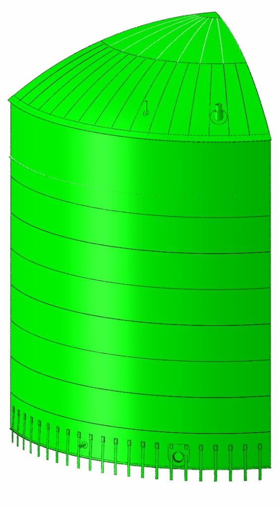
A supplemental FFS evaluation consisting of critical flaw sizing and crack growth study was performed to assess the susceptibility of tank components to SCC to refine additional inspection requirements. Elastic stress analysis using FEA was performed to determine the through-wall stress distributions at critical locations in the tank. An overview of the model geometry is provided in Figure 2. E2G’s focus was on the highest stresses on the inside wetted surfaces of the tank. A fracture assessment in accordance with Part 9 of API 579 was performed which highlighted the annular plate at bottom corner joint as the most limiting location for ammonia SCC (see Figure 3). Probabilistic analysis of crack growth was also carried out to guide a required inspection interval. Results of a Monte Carlo analysis with 20,000 simulations indicated the risk of failure of the tank bottom corner joint with an initial detectable flaw reaches the risk target after 13.4 years (see Figure 4).


Given that the API 581 RBI results were driven by a high consequence of a potential ammonia release and the results of the FFS analysis demonstrated acceptable risk for an interval of over 13 years, E2G recommended the tank follow the recommendations of the Fertilizers Europe RBI assessment and to inspect the tank on an initial maximum inspection interval of 10 years. E2G recommended performing acoustic emission (AE) testing to eliminate the risks of opening and warming an ammonia storage tank for an internal inspection. E2G also provided guidance on critical tank locations that should be a focus of the AE testing, such as the bottom corner joint.
Conclusion
E2G’s experiences with ammonia storage tanks suggest that the risks associated with traditional out-of-service inspection requiring emptying and warming a refrigerated ammonia tank for entry often outweigh those of the alternative nonintrusive approach. It is important to review the tank’s history and susceptibility to damage when creating an inspection plan that properly minimizes lifetime risk of the tank. The use of API 581 RBI, Fertilizers Europe RBI, and FFS analyses can provide greater insight into the likelihood of failure, which can then be utilized to develop the proper inspection strategy and interval for a refrigerated ammonia tank. E2G offers a comprehensive solution where the value from a fracture-based FFS assessment can be effectively integrated with the RBI assessment results through the implementation of probabilistic analysis.
References
1. Fertilizers Europe, Guidance for Inspection of Atmospheric, Refrigerated Ammonia Storage Tanks, 2008 Edition, Issue 2014. Avenue E. van Nieuwenhuyse 4/6, B-1160, Brussels, Belgium.
2. Nyborg, R. and Lunde, L., “Life Prediction of Ammonia Storage Tanks Based on Laboratory Stress Corrosion Crack Data,” Application of Accelerated Corrosion Tests to Service Life Prediction of Materials. ASTM STP 1194. American Society for Testing and Materials, Philadelphia. 1994.


