Determining the cause of a change in machinery condition can be a difficult task, and vibration analysis is a valuable tool to help determine the reason for these changes. This article presents a case study to determine the cause of high vibration levels and low reliability of a vertical pump. The source of the problem was identified as a structurally compliant discharge head and motor adapter connection; increasing the stiffness of both of these items was recommended to resolve this problem. This case study utilized standard vibration analysis, orbit analysis, operating deflection shape (ODS)/modal testing, and rotor dynamic modeling.

Background
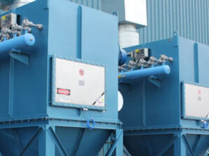
The vertical pumps (Figure 1) were placed into liquid natural gas service in October 2021 and operated with high vibration levels following the initial start-up. The pumps were originally supplied with 25 stages (impellers). In this configuration, the pump produced higher pressure and flow than required by the operator. Operational adjustments were made to reduce this excess head and flow to suitable operating ranges for the piping system. Operating in this configuration resulted in poor reliability with the motors.
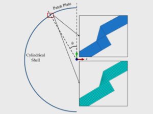
In January 2022, two stages were eliminated, leaving the pumps with 23 stage impellers. When the de-staged pumps were re-installed, a tuning plate was installed between the motor base and top of the discharge head to decrease the structural natural frequency of the motor and pump head assembly, since there were concerns about the pump running at a structural natural frequency. Figure 2 shows the location and assembly of the tuning plate.
When the modified pumps were placed into operation, the motor and pump condition improved, and vibration amplitudes were considerably decreased from prior levels. However, in November 2023, vibration levels increased on one of the pumps, and higher noise levels were observed. This pump was shut down and inspected for damage. During inspection, wear and scoring were observed on the pump shaft and throat bushing in the bottom of the seal chamber. The throat bushing was replaced, and the pump was placed on stand-by service until it could be completely disassembled and inspected. In order to determine the source of the problem, E2G performed a machine diagnostic evaluation as described below.

Field Vibration Analysis
Common measurement locations for housing vibration for vertical pumps are on the upper motor bearing and at the lower motor bearing/upper pump discharge head. Measurements were obtained at these locations, and amplitudes are summarized below in Table 1. The dominant frequency of vibration was at the pump running speed (3582 rpm or 59.7 Hz). The radial vibration amplitudes measured at both locations exceeded the guidelines in Hydraulic Institute Standard 9.6.4 [1].

Permanent proximity probes were not installed on this pump, so E2G installed a set of portable proximity probes and measured the shaft vibration levels. The measured shaft vibration amplitudes were as high as 6.15 mils pk-pk, which is considered unsatisfactory for long-term continuous operation per ISO 7919-3 [2]. The proximity probe data was also used to generate orbit plots for evaluation of shaft motion during steady state operation. The orbit plot in Figure 3 shows evidence of two inner loops during a single revolution of the shaft. These loops typically indicate non-synchronous vibration content, such as a rub-bounce condition, and evidence of rubbing between the shaft and throat bushing was observed during the November 2023 inspection. Therefore, it was concluded that the internal loops were evidence of these rubs.

Traditional accelerometer-based data was also collected and used to determine the ODS of the pump and piping assembly. The shape and relative magnitude of the motor and discharge head deflection at operating speed are shown in Figure 4. There is a significant amount of deflection at the throat bushing area, which aligns with both the high shaft vibration amplitudes and orbit shape as well as the shaft and bushing damage observed during the shutdown inspection. Modal testing was completed after the pump was shut down, and this data showed that the structural natural frequency nearest to running speed was at 44 Hz and had a similar mode shape to the ODS as shown in Figure 4. Since the separation margin between this natural frequency and the operating speed of 59.7 Hz was 26%, the high vibration levels were not attributed to resonant amplification. Annex E of HI Standard 9.6.8 [3] indicates that a separation margin of 10% is usually satisfactory to avoid unacceptable vibration amplification for all modes.

From the modal test data, the stiffness of the motor-to-discharge head was determined to be 5,100 lbf/in, which is considered to be a relatively flexible joint. The ODS and mode shape also show that the lack of stiffness of the discharge head contributes to the problem as well. The excessive structural compliance was identified as the root cause of the high vibration levels and the shaft-throat bushing rub. To resolve this problem, E2G recommended increasing the stiffness of the discharge head and motor-discharge head connection while ensuring sufficient separation margin to running speed.
To increase confidence in the conclusions, E2G built a simplified rotor dynamic model of the pump and compared the measured coastdown data against the calculated Bode plot of the model. This data is shown in Figure 5 and provides a good match to the measured structural natural frequencies of 28 Hz (1675 rpm) and 43 Hz (2550 rpm). This simple rotor dynamic model provides confirming evidence of the conclusions and recommendations.

Summary
This article provides a case study of diagnosing the root cause of excessive machine vibrations. Vibration analysis is a powerful tool to help understand the source of the problem and identify a high-confidence solution to fix it. Casing and shaft vibration analysis, orbit analysis, ODS/modal testing, and rotor dynamic modeling were used to identify the problems and verify the proposed solution to increase the discharge head stiffness and increase the motor-discharge head connection stiffness.
If you have any questions for the author, please submit the form below:
References
- [1] ANSI/HI 9.6.4-2016, American National Standard for Rotordynamic Pumps for Vibration Measurements and Allowable Values, Hydraulic Institute.
- [2] BS ISO 7919-3:2009+A1:2017, Mechanical Vibration – Evaluation of Machine Vibration by Measurements on Rotating Shafts.
- [3] ANSI/HI 9.6.8-2014 (R2021) Rotodynamic Pumps – Guideline for Dynamics of Pumping Machinery.