Hydroprocessing equipment, such as hydrotreaters and hydrocrackers, are a vital path for increasing refinery yield of high-value products. The hydroprocessing effort involves the introduction of hydrogen into oil streams in the presence of a catalyst, producing cleaner fuels and allowing for the further processing of heavy end products. A variety of catalysts are employed depending on the treatment specified, i.e., desulfurization, denitrogenation, dearomatization, etc.
Typical hydroprocessing equipment (or reactors) include fixed catalyst beds to support the solids in the flow path. Designs may include single or multiple beds where each bed is supported by an internal mechanical composite structure. The support structures may include support beams, grids, screens, etc. to withstand the weight of multiple layers of catalyst and inert packing. A typical catalyst bed composition can be found in Figure 1.

As the reactor operates, build-up of coke or the deposition of undesirable products on the catalyst surface reduces the efficiency of the reaction but also increases the loading on the catalyst bed support structure. These two design considerations influence the run life of the reactor, dictating when costly shutdowns and catalyst change-outs are required. The build-up on the catalyst contributes to greater weight loading but also restricts flow of the oil stream through the catalyst bed, leading to an increased differential pressure (ΔP) across the bed. The ΔP across the bed may reach limiting conditions prior to deactivation of the catalyst. Note that an increase in process temperature may extend the life of the catalyst, but this may not have an effect on the increase in ΔP.
Maximizing the runtime of a hydroprocessing reactor requires knowing the limits of the bed support ΔP. The ΔP will be a function of the packing characteristics of the bed, the amount of liquid hold-up, coke build-up, and operating conditions of the reactor (pressure and temperature). The limits on ΔP will be a function of the bed support geometry and materials of construction. Since the bed support is a composite structure, any one of the components making up the bed support could be the limiting component.
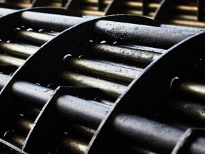
Bed supports can vary in design but typically include beams, structures to support the beams (chairs or rings), grids, and a screen. A typical catalyst bed detail is found in Figure 2, showing the arrangement of grids within the support beam structure. Often the minor components (grids or screens) can be the limiting component. A sketch and photo of a layer mesh screen can be found in Figure 3 and Figure 4.


The assessment of the composite support structure is best accomplished through a finite element analysis (FEA) which will consider the interaction of all the components. Elastic-plastic analysis can take advantage of the strain hardening characteristics of the materials, resulting in a less conservative result than an elastic analysis typically used in the original design. The following case study describes the analysis and results of a typical hydrocracker reactor bed.
This case study involves a hydrocracker reactor designed in accordance with ASME Section VIII Division 2 (ASME VIII-2). The owner-operator of the vessel was seeking to increase the allowable ΔP across the catalyst bed to delay the need to shut down. The reactor design details are as follows:
| Design Pressure: | 3.255 psig |
| Design Temperature: | 850°F/454ºC |
| Shell Material: | SA-336 Grade F22 (2.25Cr-1.0Mo) |
| Shell Thickness: | 12.6875 inches/32.226 centimeters |
| Design CA: | 0.171 inch (308L Weld Overlay)/ 4.343 millimeters |
| Shell Diameter: | 13 feet/3.96 meters |
| Bed Support Material: | SA-240-321 |
| Contents Specific Gravity: | 0.95 |
Additional operational details impacting bed loading are as follows:
| Liquid Hold-up in Bed: | 45% by volume |
| Increase in Bed Weight Due to Coking: | 40% |
Analysis involves identifying the loading on the support structure components due to the catalyst, liquid hold-up, coking weight, and ΔP. Generally, the weight loads are considered static, and therefore dynamic effects are ignored. Once weight loads are applied to the model, the analysis can be run to failure with increasing ΔP to determine the maximum acceptable differential.
Proper load distribution among the components that make up the support structure is critical. Beams may carry majority of the load, but the beam load and any remaining load are transferred to support lugs or a support ring and ultimately back to the vessel shell. In this case study the weight loading resulted in an effected pressure on the cross-sectional area of the shell of 7.7 psi. The beams were determined to be the limiting components based on a total pressure of 73 psi. This resulted in a limiting ΔP of 65.3 psi (73-7.7 psi).
While the safety margin for ASME VIII-2 is 2.4, ASME VIII-2 does not specifically address safety margins for internal components; therefore, a reduced safety margin could be acceptable based on the governing allowable risk tolerance. Assuming a safety margin of 1.5, the maximum allowable ΔP across the bed would be 43.5 psi. Selection of safety margins should consider the accuracy of the instrumentation used to measure the ΔP and the tolerance of any assumptions used in the analysis.
General inspection recommendations include a thorough inspection of all support components to confirm that no deformation, cracking, or other damage has accumulated from previous operation. The structural integrity of the support bed should be reevaluated if existing damage is identified.
Future inspection should include full visual inspection of the support assembly for any signs of potential cracking or local deformation with particular attention paid to component attachment locations, welds and weld heat-affected zones (HAZs), and local features producing geometric stress concentrations.
Locations experiencing elevated stresses, such as those shown in Figure 5, should also be areas of inspection focus: midspan of the longest-span grids, midspan of beams, beam flange-to-web welds, the blend radii between the bed support rings and the reactor shell, and the welds associated with the beam support blocks.

The original design analysis of the catalyst support structure may no longer be applicable based on changes in bed design over the life of the reactor to accommodate process changes. Additionally, original design calculations may not have considered more aggressive operating conditions currently employed to increase yields. Catalyst bed support structures should be reevaluated if the loading conditions become more severe or if the design ΔP becomes a limiting factor in catalyst bed remaining life.
Stress analysis is a great tool to understand the limits of your reactor internals including knowing which components limit and by what margin. A greater understanding of the reactor limits may allow for fewer costly shutdowns by extending the runtime of the reactor catalyst beds. Equity has extensive FEA and industry code experience to support owner-operators in understanding the operating limits of their equipment.
If you have any questions for the authors, please submit the form below: