Process facility owner-users spend a tremendous amount of time, effort, and money managing maintenance programs to keep equipment in safe operating condition for as long as possible. However, even the most well-managed maintenance and inspection programs cannot prevent the inevitable need to repair, replace, or alter equipment. When these activities are necessary, it is vital that they can be carried out in a safe and timely manner to return the production unit to reliable operation without incident or delay. Advanced analysis can be leveraged to support these efforts by, among other things, evaluating weld repair plans and post-weld heat treatment (PWHT) applications, validating rerate conditions where documentation is lacking, and ensuring structures and foundations can adequately support changing loads as a facility evolves over its operational lifespan. In this article, case studies are presented demonstrating how Equity Engineering utilizes advanced analysis methods to facilitate a wide variety of post-construction activities.
Weld Repair Simulation
Almost any steel component that finds use in a mechanical engineering environment has some amount of welding associated with its construction and installation. Furthermore, weld metal deposition is frequently used as a strengthening mechanism for service-degraded components. Many guideline documents and standards exist to qualify the strength of bonding for welding procedures, and, in practice, weld procedures are qualified through both nondestructive and destructive testing techniques; however, comparatively little attention is given to the potential for distortion that can result from welding procedures.
Distortions generated by welding procedures are particularly insidious for in-service components that are being repaired through weld deposition, as in many cases the weld repair scope is being completed during a shutdown condition that typically renders it a critical path item. If a weld repair results in an unacceptable level of distortion (see the limits of API 579-FFS-1 Part 8), the component will require a subsequent fitness-for-service (FFS) analysis prior to returning to operation. This can extend a schedule by multiple days, which is financially punishing. Completing a pre-emptive weld deposition analysis can identify distortion and residual stress issues before they happen in the field, and a mitigation strategy can be developed to minimize risk.
Consider the Following Weld Repair Scenario
A large vacuum tower has significant metal loss at an upper conical shell section of approximately 800 square feet. The tower is designed to ASME VIII Division 1, largely comprised of SA-516-70 carbon steel, and has a full vacuum design condition at elevated temperatures. If the thickness of the vessel is to be restored through weld deposition, there is a high likelihood of distortion, which could force a follow-up FFS analysis and extend the schedule for this procedure by several days – in the middle of a plant turnaround.
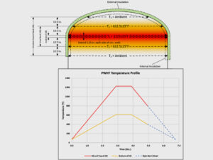
API-579-FFS-1 Part 8 rules state that the permissible shell distortions for a conical section under vacuum conditions are limited. In this example, the allowable radial distortion for the cone falls on the
e = 0.8 × t curve of API 579 FFS-1 Part 8 Figure 8.12 for the entire vertical length of the cone (Figure 1). Given an average base thickness of 1.33 inches and a weld metal thickness of 0.125 inches, the calculated “equivalent thickness” for conic sections (note 6 of Figure 8.12) is teq = t / cos(ɑ) = 1.60 in (alpha for the current geometry is approximately 25°). This sets the allowable radial deviation from true circle for the cone at 1.28 inches within the weld overlay region.
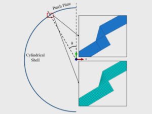
Enter Equity Engineering’s Mechanical and Structural (M&S) Team – we conducted an initial study using an axisymmetric model for the weld overlay (Figure 2– left side). The model was analyzed using progressive partial element activation techniques to deposit the weld overlay metal following a predefined weld procedure. The axisymmetric results were then mapped using an equivalent strain energy basis to a complete 3-dimensional shell model of the entire top region of the vessel (Figure 2 – right side), and a final post-welding distortion field was computed (Figure 3).
The analysis predicted that there would be considerable risk of inducing weld distortion above the API-579-FFS-1 allowable values. Several mitigation techniques were simulated, including modified weld torch properties (travel speed, voltage, amperage), sequencing, deposited thickness per layer, and external stiffening. In this case, external stiffening of the cone structure proved to be the most effective and reduced the predicted distortion by over half an inch (Figure 4). This recommendation empowered the client to efficiently perform this repair without causing excess distortion, saving them valuable time and resources during an outage where delays quickly turn into lost profit.


Advanced PWHT Analysis
Post-construction PWHT is often associated with welded repairs of damage on equipment or piping; therefore, steps should be taken to ensure that the PWHT process does not unintentionally induce further damage. The first part of this article discussed utilizing advanced analyses to prevent damage and distortion due to the welding process; in this section, we will similarly discuss how advanced analyses may be used to prevent damage during the subsequent PWHT process.
Several critical issues can result from improperly performing PWHT, especially of the local non-circumferential (or spot) PWHT layout type. In particular, it is possible that permanent residual stresses are created elsewhere in the equipment due to thermal expansion which may result in local buckling or bulging of the equipment, as well as increased susceptibility to cracking. This is particularly important for pieces of equipment that are sensitive to buckling instabilities, operate in cyclic service, or operate in stress corrosion cracking environments. A fully circumferential local PWHT layout is preferred and is an acceptable method of stress-relief per various codes such as the ASME Boiler and Pressure Vessel (B&PV) Code and the National Board Inspection Code (NBIC). Non-circumferential local PWHT layouts are not specifically described in the aforementioned codes, and therefore special care is required when implementing a non-circumferential local PWHT plan. To understand the fundamental differences between the two layouts, Figure 5 shows a nodal temperature plot of a non-circumferential local PWHT layout of a nozzle repair on the left and a circumferential local PWHT layout on the right.

An example of distortion caused by a failed non-circumferential local PWHT is shown in Figure 6 below.

Can I Qualify Local Non-Circumferential PWHT Layouts?
Various recommendations for using local non-circumferential PWHT layouts are provided in WRC Bulletin 452 and API 510. Generalized rules for local non-circumferential PWHT layouts, however, do not currently exist, and a common requirement in WRC Bulletin 452 and API 510 is that use of such layout must be individually evaluated by a competent pressure vessel engineer. Finite element analysis (FEA) is typically employed to effectively quantify overall and local strains and distortions resulting from a local non-circumferential PWHT (which is a requirement of API 510), especially when the region is local to stress discontinuities such as head-to shell or nozzle junctions.
In general, a steady-state thermal-mechanical analysis utilizing high-temperature elastic-plastic material properties will result in the most robust characterization of the resulting residual stress, plastic strain, and potential for distortion due to the local PWHT. Beyond the applied thermal load, appropriate loadings such as weight and significant piping or platform loads should be included in the model, as well as pertinent boundary conditions such as fixed saddle supports that may restrain thermal growth. Because limited guidance exists for the physical layout of local non-circumferential PWHT plans, determining an acceptable layout depends on previous experience and/or trial and error. Per WRC Bulletin 452 paragraph 6.1, a circular soak band at a radial distance of 2.5√Rt inches from the edge of the attachment weld is specified, with additional requirements for proximity of the half-temperature location to the weld provided in AS 1210. However, recent work has shown that these requirements may be too conservative, further justifying the need to perform a case-by-case analysis. The guidance from AS 1210 may be used as an initial layout guidance which can then be iteratively fine-tuned via FEA. In Equity Engineering’s experience, a layout which extends further in the circumferential direction than it does in the longitudinal direction is an effective lever to pull when trying to reduce residual stresses and strains. Considering that non-circumferential PWHT layouts are not a Code-defined process, there are no published Code criteria detailing acceptable resultant stress or strain limits from a PWHT process. Our experience further indicates that limiting the residual plastic strain to 2% results in successful PWHT operations without thermally induced micro-cracking. Even if FEA results indicate residual plastic strains less than 2%, Equity Engineering recommends completion of a parametric study with varying PWHT layouts to find the layout with the least amount of predicted residual stress and strain.
In conclusion, local non-circumferential PWHT layouts may be used if a fully circumferential local PWHT layout is not practicable. However, a detailed engineering assessment by a competent individual must be completed to avoid the commonly documented introduction of further damage due to improper implementation of local non-circumferential PWHT.
Structural Analysis for Changing Loads
Circumstances inevitably arise that require replacement or significant alteration of process equipment. Equipment may be damaged beyond repair, or a significant repair is needed that necessitates a follow-up hydrotest. In these situations, the last major question that an owner-user often asks is “can my existing structural system support these new loads?” Equity Engineering can answer this question by combining advanced analysis techniques with intimate knowledge of both mechanical equipment and structural engineering practice.
Case Study: Heater Box Stack Replacement
A client planned to replace a stack supported by a heater box structure during an upcoming outage. The new stack was about 20% heavier than the original owing largely to changes in stack design codes (ASME STS-1) and design loading procedures (ASCE 7). This meant that both vertical and lateral design loads for the new stack were significantly greater than what would have been required in the original design. Significant modifications to piping were also planned, resulting in even more weight that the structure needed to support. In addition to assessing the stack and piping for code compliance, Equity Engineering was tasked with determining if the existing heater box structure and foundation were capable of safely supporting these increased loads.
A structural model of the heater box was developed that incorporated reaction loads from the piping and new stack, as well as wind, weight (dead and live loads), and seismic loading from the heater box itself (Figure 7). This structure was unique from a structural engineer’s perspective in that its construction for mechanical purposes provided what are effectively undersized steel plate shear walls—a common type of lateral force resisting system (LFRS) in buildings—acting in parallel with a braced frame LFRS. Although the structure initially appears building-like, the loads largely come from equipment supported at the top, resulting in atypical demands relative to a small building of similar proportions. The superstructure was assessed using AISC 325 allowable strength design (ASD) methodology. Reaction loads at the strip footings were used to assess the foundation per ACI 318, and principles of geotechnical engineering were employed to evaluate the bearing capacity of the underlying soil. This assessment was ultimately able to endorse the proposed modifications. However, this required a nuanced understanding of how structural design codes and design loading have evolved over time, as well as building code interpretations of these changes as applied to existing structures to allow for some relaxation of new design requirements without compromising on overall structural reliability. In evaluating this structure, Equity Engineering’s depth and breadth of knowledge of both the mechanical and structural systems provided understanding of all relevant demands and potential limit states.

Field Hydrotest
Another relatively common scenario encountered by owner-users is the need to perform a field hydrotest for equipment that was originally hydrotested in the shop. This situation can arise due to significant vessel repairs or to facilitate catalyst cleanout in reactors. The potential issue here is a lack of documentation on the support and foundation design indicating that the hydrotest load (in combination with any other design loads, e.g., wind) was considered in the original design. This is particularly complicated in situations where a single foundation system supports multiple pieces of equipment, which is further exacerbated when there is little to no documentation of any underlying foundation piles or soil properties. Equity Engineering has experience applying engineering best practices and conservative assumptions to these scenarios to safely estimate the load carrying capacity of equipment support structures, foundations, and underlying soil, allowing for safe field hydrotest even in cases where information is limited. Such assessments often fall back on basic engineering principles, such as the shear and moment diagrams shown in Figure 8 for a mat foundation supporting two large reactors that were planned for simultaneous flooding (the third vessel is significantly smaller than the others and was not flooded). Demands at critical sections in the foundation are obtained from this analysis and assessed using ACI 318 to determine if the foundation can adequately carry the shear and bending demands. A strain compatibility diagram for performing this type of analysis on a doubly reinforced concrete section is presented in Figure 9.


Conclusion
Managing fixed equipment presents an ongoing challenge in facilities across many industries and around the world. Repairs and alterations are an essential part of this maintenance, allowing for continued use of existing equipment that has experienced damage or any type of significant alteration potentially affecting structural support conditions. Equity Engineering combines state-of-the-art analysis with extensive engineering experience to support safe and reliable post-construction work to meet our clients’ needs.
Please submit any questions for the authors using the form below: