Effect of Sigma Phase on FCC Internals
Overview
Sigma phase embrittlement primarily affects austenitic (300-series) stainless steel fluid catalytic cracking (FCC) cyclone and other internal welds in FCC regenerators. This mechanism may also affect the 300-series base material in the regenerator internals after a long operating time (>15 years), and in rare cases, might be a concern in reactors with exceptionally high operating temperatures. This mechanism results in a loss of toughness and ductility at ambient temperatures (<500°F / <260°C) and a reduction in creep ductility (increased propensity for creep cracking) at operating temperature. Ferrite controls for 300-series filler metals are critical in minimizing the negative effects of sigma phase. For in-service 300-series welds, LPI of welds and metallography (ideally a removed sample as opposed to in-situ) can be used to assess the amount of embrittlement. Weldability testing prior to attempting repairs is recommended, so that special procedures to mitigate the effects of embrittlement can be developed if necessary.
Overview of FCC Internals
FCCU Reactor
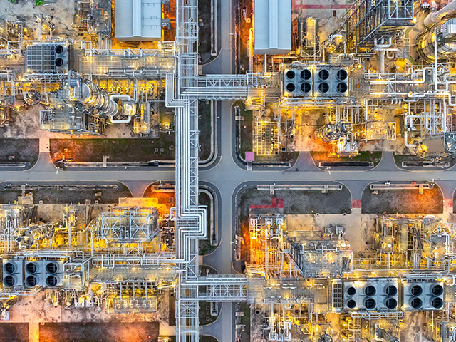
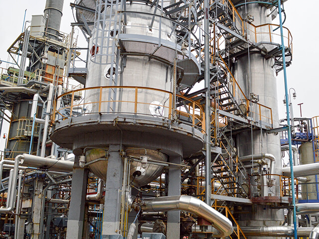
Hot (1300°F / 704°C) regenerated catalyst flowing up a riser is sprayed with the preheated incoming feed to initiate the cracking process. The combined stream in most FCC units will be 950-1000°F (510-538°C), and most of the reaction occurs within the riser. Cracked hydrocarbon vapors and catalyst enter the reactor where a large amount of catalyst drops to the bottom of the vessel on its own. The vapors and remaining entrained catalyst enter primary cyclones and then secondary cyclones which use centrifugal force to knock out most of the remaining catalyst. Each primary cyclone typically has a tangential bell-shaped inlet; the pressure difference between the reactor vapor space and the main fractionator pushes the vapor with entrained catalyst into the primary cyclone inlet, where the heavier catalyst particles impinge on the refractory-lined wall and drop down the cyclone while the vapor is drawn off the center top of the cyclone and directed to a secondary cyclone (which operates on the same principle). This arrangement is visible in Figure 1 – primary cyclones in the outer ring and secondary in the inner ring. Vapor from the secondary cyclone outlet enters the plenum and then the overhead line to the main fractionator. The spent catalyst (coated with coke) flows down over a stripper section where steam is used to strip residual hydrocarbon off the catalyst before the catalyst is flowed down to the FCCU regenerator.
Reactor cyclones operating below 1000°F (538°C) are most commonly carbon steel, but other alloys including 1.25Cr-0.5Mo and Type 405 SS are occasionally used. In some less common cases with reactor operating temperatures above 1000°F (538°C), 300-series SS (namely 321) have been used. The inside of cyclones (including inlet, duct between primary and secondary, and sometimes the plenum) are lined with erosion-resistant refractory anchored via a hex mesh. The outside surfaces of these internals may or may not have hex mesh and refractory.
FCCU Regenerator
The spent catalyst is fluidized as it enters the bottom of the regenerator. Here the bed sits on top of a combustion air distributor (grid or pipe distribution) where a controlled burning occurs to remove coke from the surface and put heat back into the catalyst. The resulting combustion vapors (including entrained catalyst) migrate up the vapor space of the vessel – where again a set of cyclones are used to remove the catalyst before the flue gas exists the regenerator – headed for waste-heat recovery and sometimes solids/fines precipitation. Two sets of regenerator cyclones are often used, but even a tertiary set may be included in some units, either inboard or outboard of the main regenerator. As in the reactor cyclones, recovered catalyst falls down diplegs back into the fluid bed. The hot regenerated catalyst overflows into a well that drops the catalyst down into a transfer line where fluidization moves the hot regenerated catalyst back to the feed riser to the reactor.
An FCC regenerator may operate in either “full burn” or “partial burn” modes. In the former, all coke on the catalyst is burned with slight excess air to produce CO2 in the flue gas. In the latter, less air is added, so that the flue gas carbon oxide is primarily CO. CO can be further combusted for better heat recovery in a CO boiler. Units with CO boilers are designed for partial burn most of the time and full burn is used (for environmental reasons) when the CO boiler is offline. Partial burn operation is at a lower temperature (typically around 1200°F / 649°C or less) compared to full burn (1300-1400°F / 704-760°C).
Regenerator cyclones and other internals including any hangers or supports are most commonly 300-series SS, particularly 304H and sometimes 321 SS. As in the reactor, the inside surfaces of cyclones and internal flue gas transfer ducts within the regenerator are lined with erosion-resistant refractory in a hex mesh anchor. The air grid at the bottom of the regenerator as well as the cyclones and catalyst well sometimes have external erosion-resistant refractory.
Sigma Phase Embrittlement and Its Effect on Material Properties
Sigma phase is a hard, brittle intermetallic compound primarily composed of iron and chromium (FeCr, about 50% of each by mass) that precipitates in stainless steels when exposed to elevated temperatures, typically in the range of 1000°F to 1700°F (538°C to 927°C). Different temperatures have been suggested for the lower end of the sigma-phase formation range: API RP 571 currently states 1000°F (538°C) but references from 10-15 years ago use 1020°F (548°C) or 1050°F (565°C), and older references typically use 1050°F (565°C) and above. Most likely, the time required for sigma formation at lower temperatures just above 1000°F (538°C) is very long (much longer than at 1050°F / 565°C). As equipment continues to age and more awareness of the mechanism develops, the lower end of the range creeps lower with new experiences being reported.
Sigma phase precipitates from the ferrite phase of stainless steels, so 300-series weld metals and castings (e.g., CF8, CF8C, etc.) are generally more susceptible than wrought (plate, pipe, tube) stainless steels. These product forms have inherently more ferrite (often intentionally to prevent solidification cracking, i.e., hot shortness) and stigmatize more quickly and to a greater extent. However, even wrought materials (which may have 3 or 4 % ferrite in their base metal) can be susceptible over prolonged exposures.
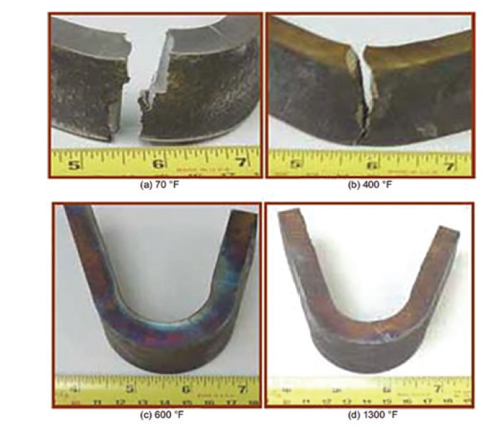
The formation of sigma phase can lead to a substantial reduction in ductility and impact toughness, especially at near-ambient temperature, making the material more susceptible to brittle fracture. This can lead to unexpected failures during shutdowns or start-ups when the material is cooled below about 500°F (260°C), where the embrittling effects of sigma phase are most pronounced. Loss of toughness below temperatures as high as 1000°F (538°C) is mentioned in API 571; however, this has not been extensive and the primary concern for reduced toughness remains at temperatures below 500°F (260°C). Figure 2 shows the effect of sigma phase on ductility and fracture propensity using bend tests of Type 304 stainless steel specimens (base metal) with 12% sigma from an FCC flue gas duct. Additionally, sigma phase embrittlement can complicate maintenance and repair activities, as the embrittled material exhibits poor weldability, making it difficult to perform effective repairs.
Sigma phase embrittlement also negatively impacts the creep life of materials. Sigma phase formation has been correlated with reduced creep ductility and rupture time. Especially for welds, increasing sigma phase content results in poor creep ductility, with much lower strain to failure than un-sigmatized welds. The relationship between time in service, % ferrite, and creep ductility is not as clear for wrought base metal, but it is generally believed that sigma phase formation reduces the strain-to-failure in creep. It has been hypothesized that sigma phase provides stress concentration points at the grain boundaries where it has precipitated. These stress concentrations can act as initiation sites for creep cracks, thereby accelerating creep damage.
Because sigma phase forms from ferrite which is commonly situated on the grain boundaries in cast microstructures, and because it is higher in chromium than the base alloy, its formation depletes Cr from the surrounding matrix. This can produce Cr-depleted areas adjacent to grain boundaries that are more susceptible to other mechanisms (oxidation, carburization, sulfidation). Oxidation or sulfidation of lower-Cr material along grain boundaries can assist creep crack initiation and growth. Sigma-embrittled material is less able to accommodate the deformation and stress relaxation that occur during high-temperature service.
Locations of Concern for Sigma Phase and Mitigation Strategies
Sigma phase embrittlement is primarily a concern in the regenerator. Reactors nearly always operate below 1050°F (565°C) even when 300-series internals are used. Notably there are other mechanisms that could result in embrittlement or cracking of 300-series internals, especially welds in reactor internals, such as 885°F (474°C) embrittlement (like sigma, this also affects the ferrite phase) and sensitization and polythionic acid stress corrosion cracking (PTASCC). For the much more common case of CS or low alloy (e.g. 1.25Cr-0.5Mo reactor cyclones), the 12% Cr (e.g. 410S) hex mesh anchor material amay be welded to the cyclones with a 300-series filler metal. These welds may be susceptible, however the temperatures are probably too low for severe sigma phase embrittlement.
Unfortunately, it is difficult to monitor for sigma-phase formation and it may only be realized to be significant when weld repairs are made difficult due to the poor ductility of the embrittled material. There is no ready non-destructive testing technique to detect the onset of embrittlement. Weldability testing prior to weld repairs on potentially embrittled SS components is suggested. In-situ metallography is difficult to use for sigma evaluation, and better success can be obtained when performed on removed samples.
Some refiners use 12 or 15 years as time period beyond which sigma embrittlement is a significant concern. After this age is reached, inspections of 300-series welds in the regenerator via liquid penetrant inspection are performed (particularly at high stress locations), and weldability testing is performed prior to repairs. In cases where the weldability is impacted by sigma embrittlement, buttering strategies can be attempted. It is not typically practical to attempt heat treatment in the field to improve weldability for sigma-embrittled components.
Preventive measures to mitigate sigma phase embrittlement include using alloys that are less susceptible to sigma formation. As expected, the focus tends to be on the weld filler selection. Ferrite controls of welds (specifications for ferrite numbers between 3 and 9 inclusive) or alternative low ferrite fillers such as 16-8-2 are often used to help limit the sigma embrittlement potential of 304H stainless steel construction by reducing the amount of ferrite initially available to transform into sigma. Some users even specify the ‘lean’ (lower Cr, Ni and Mn content) variant of 16-8-2 filler to further reduce the potential for sigma formation. In some cases, proactive replacement of older components that are known to be more susceptible to sigma phase embrittlement may be necessary to prevent unplanned shutdowns and ensure the reliable operation of the FCC unit.
Further reading:
- C.A. Shargay and A.R. Smith, “Materials Selection for FCCU Cyclones” NACE Corrosion 2003, Paper 03646
- J. L. Hau, “Sigma Phase Embrittlement of Type 304H Stainless Steel After FCCU Service” NACE Corrosion 2017, Paper 09140
- J. Hau & A. Seijas, “Sigma Phase Embrittlement of Stainless Steel in FCC Service” NACE Corrosion 2006, Paper 06578
- API RP 571, “Damage Mechanisms Affecting Fixed Equipment in the Refining Industry” 3d Ed., 2020.
- API TR 942B “Materials, Fabrication, and Repair Considerations for Austenitic Alloys Subject to Embrittlement and Cracking in High Temperature 565 degrees C to 760 degrees C (1050 degrees F to 1400 degrees F) Refinery Services, First Edition” 2017
- P. Prueter, “Metallurgical Embrittlement Detection” Damage Control. Inspectioneering Journal, March/April 2024.