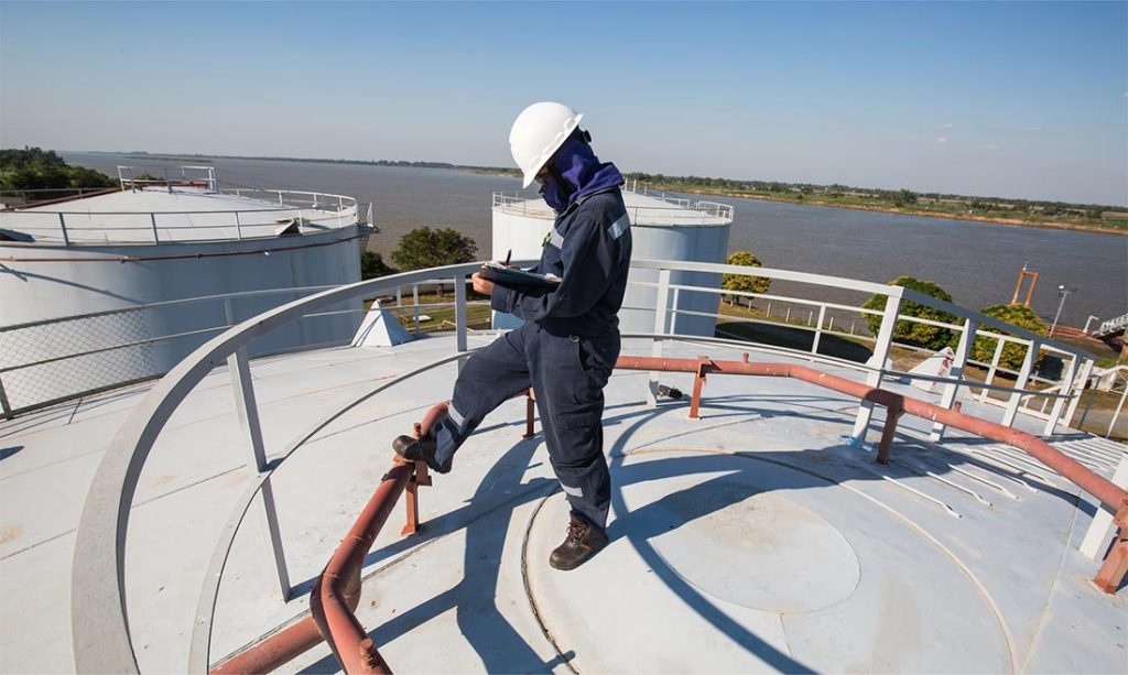
Aboveground storage tanks are susceptible to damage from many factors, including (but not limited to) environmental loads, process upset conditions, strength reduction due to metal loss, tank settlement, or some combination thereof. This damage often manifests as buckling of the tank shell, which is thin relative to its large surface area. Many tanks in service today have a fixed “cone” roof supported by structural members; much like the tank shell, these members are also susceptible to buckling failures as they must support loads while spanning long distances with minimal intermediate bracing. Buckling of tank roofs can lead to significant distortion of the tank shell, particularly localized in the top courses and at rafter connections. This shell distortion can create concerns regarding the capability of the shell to hold full product load (Figure 1).
Considering the tank shell and roof structures acting in tandem presents a challenge when performing Fitness-For-Service (FFS) work on damaged tanks, because the large buckling deformations in either system can induce failures in the other, making it difficult to discern a root cause of failure. Furthermore, experience has shown that engineers sometimes overlook some design basics when devising connection and bracing schemes in fixed roof structures.
This article briefly outlines a recent FFS project performed by Equity’s Mechanical and Structural Engineering team where many of the aforementioned issues contributed to a tank roof failure.
Tank Distortion Failure Analysis
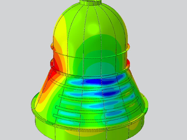
The tank in this case study had significant distortions on both the upper and lower portions of the shell, as well as a significant depression in the roof. This damage was discovered after a storm which produced design-basis wind gusts and heavy rainfall. Additionally, significant blockage was found in a roof vent which may have caused unwanted internal pressure conditions. A labeled rendering of the structural analysis model created to analyze the roof structure is shown in Figure 2. Structural analysis of the roof support system was performed using the commercial analysis program STAAD. The analysis of the rafters, girders, and columns indicated these members were appropriately sized per the governing codes (API 650 and AISC 360). However, upon further analysis, the rafter-to-girder “clip” connections were found to be extremely weak considering any bending moment or axial force demands coming from the rafters.
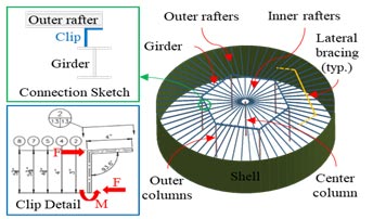
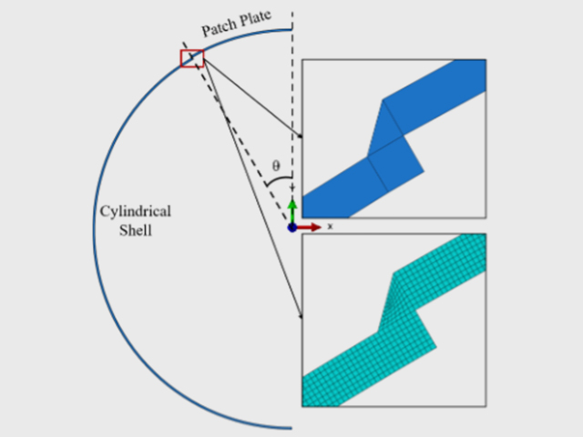
The detail of these connecting members for the outer rafters in Figure 2 shows that the vertical legs of these clips vary in height to maintain a consistent top-of-steel elevation for all rafters to support the cone-shaped roof plate assembly; the tallest clip leg is 5.375”, which is required for the rafters which frame into the girders near mid-span. These rafters also span the longest distance between the girder and shell, making them the most susceptible to lateral torsional buckling (LTB) when subjected to flexural demands.
The height of the clip increases the lever arm of any axial forces transferred from the rafters to the girder, which must be resisted via weak-axis bending of the vertical clip leg.
Analysis of this connection indicated that the tallest clips were expected to fail (full development of plastic moment capacity in vertical clip leg) under design-basis loading; this is believed to be the first aspect of the roof structure to fail, although it is unclear if this caused—or, conversely, was caused by—the shell buckling. In either case, subsequent damage to the roof structure resulted from the failure of this connection. Upon failure of the taller clip connections, the associated outer rafters lost contact with the roof, and the loads coming from the roof (weight, pressure, etc.) had to be accommodated by the neighboring rafters, increasing demands beyond those for which they were designed. Simultaneously, the sagging of rafters with failed connections pulled down the lateral bracing bars attached to the top flanges of all rafters at their approximate mid-span; these bracing members are essential for preventing lateral torsional buckling (LTB) in slender beams subjected to flexural demands, and the loss of this bracing significantly reduced the capacity of each neighboring rafter as the failure continued to propagate. After this initial failure mechanism was proposed to the client, an internal inspection was carried out which confirmed that all outer rafters on one half-side of the tank (180-degree arc) exhibited LTB behavior and failed clip connections, among other forms of damage. A suitable clip replacement design was provided.
Conclusions from the Tank Distortion Assessments
Several conclusions were drawn from this case study. The stability of tank shells and fixed roof structures depend upon each other. Roof distortions can cascade into further roof failure and even shell distortion or failure, and shell distortions can cascade into subsequent roof system distortion or failure. Both systems are very flexible and subject to buckling, and a local failure can become global. It is important to identify load paths in these structures and determine if there are any “weak links.” It is also important to understand controlling failure mechanisms – LTB of structural elements, clip failures, local shell buckling, etc.
This case study is indicative of the complexities which can arise when considering interactions between the shell of an aboveground storage tanks and its fixed roof structures. This and similar FFS projects that Equity has performed have proven that expertise in structural design, connection detailing, and buckling phenomena are necessary to fully assess the integrity and determine a safe and reliable path forward for tanks and similar types of fixed equipment and piping whose interaction with their structural components cannot be ignored, whether the analysis is on a proactive basis or after damage has occurred.
Equity is putting this knowledge into practice by working with our clients to mitigate the potential for this type of cascading failure for in-service tank roof systems, including recommending stronger rafter connections, more robust lateral bracing, and stricter rafter structural member slenderness limits. As we have done many times in the past, we are updating our own internal Equity Engineering Practices (EEPs) based on the lessons learned from this project. We are also evaluating the need for proposing a change to API 650 requirements for fixed roof structural designs. Based on our experience and expertise in performing these types of analyses, Equity is uniquely suited to provide insights in to how to improve the performance of aboveground storage tanks.