Boilers are vital for any industrial process that relies on steam for heat, pressure, or power. Without a reliable steam source, processes can stall until everything’s back on track. Regardless of the boiler type, they all face similar corrosion issues that disrupt predictability—most of which are related to boiler feedwater (BFW) chemistry. Knowing the most common corrosion challenges might prevent a shutdown.
Boiler Types
Most steam-generating equipment in a refinery or process plant falls into one of three categories: package boilers, waste heat boilers (WHBs), and convection coils in process-fired heaters that double as steam generators. Though less common, some plants may have larger heat recovery steam generators (HRSGs) as part of co-generation units, large standalone auxiliary boilers, or large fossil-type boilers.
Package boilers are pre-built, compact, and self-contained, designed for fast installation and solid performance. They are most commonly water-tube (water/steam inside the tubes) as opposed to fire-tube (combustion gases inside the tubes). Water-tube boilers tend to be larger, more efficient, and built for higher pressures than fire-tube. Inside package boilers, there is a water inlet, often an economizer coil to preheat cool feedwater before it enters the drum, a steam drum (near the top and stores steam and water), a mud drum (near the bottom and gathers sediment, sludge, and impurities), a combustion heat source, a combustion gas outlet, a water wall (tubes with water surrounding the combustion zone), and a steam outlet. The saturated steam off the steam drum may route through one or more superheater coils to generate superheated high-pressure steam. The 600 lb (272 kg) water-tube boiler is considered the workhorse of industrial steam systems.
WHBs operate similarly to package boilers, the difference is that the heat energy source is from hot process gases or effluent streams instead of primary fuel combustion. WHBs use water to “soak up” excess heat in the process that can’t be easily transferred back into process streams directly. WHBs are thus more energy efficient, translating to lower fuel costs and emissions. They’re usually fire-tube (process gases tube side), not water-tube.
Convection coils in process-fired heaters aren’t boilers exactly but exist for the same purpose of generating steam. Simply, they are water-filled tubes that run through the convection section of fired heaters and typically feed into a steam-disengaging drum that connects to the steam supply. Like WHBs, steam-generating convection coils in process-fried heaters help to minimize energy consumption. The circulating water is usually lower temperature and higher heat capacity than the process fluid which the furnace is intended to heat and is therefore able to “soak up” more of the excess heat from the still-hot flue gases after they are no longer able to meaningfully heat the process coils.
Common Boiler Damage Mechanisms
Boilers operate under high temperatures and pressures, making them susceptible to several damage mechanisms that compromise reliability. The most noteworthy issues correlate to BFW quality and lack of preventative maintenance. Some of the most common damage mechanisms associated with boilers are the following:
- creep/stress rupture
- steam blanketing & short-term overheating
- acid phosphate corrosion
- caustic gouging
- flow-accelerated corrosion
- oxygen pitting
- flue gas dew point corrosion
- oxidation
- caustic stress corrosion cracking (SCC)
- chloride SCC
- hydrogen damage
- dissimilar metal weld
- thermal fatigue
- galvanic corrosion
Creep is time- and temperature-dependent deformation of material below its elastic yield strength. Creep, or “stress rupture,” occurs due to prolonged exposure to high temperatures and stress. When the stress and temperature are within design levels (or are close enough to design levels that damage is slow and deformation/failure occurs over many years), the term “creep” is used. When temperatures or stresses are higher (well outside of design levels, such as from flame impingement) and failure occurs in months (or less), the term “stress rupture” or “short-term overheating” is used. Material deformation starts as voids at grain boundaries. These voids grow into cracks, which accelerate failure. Detecting creep damage is challenging until the later stages, where signs such as cracking and bulging become evident in areas exposed to extreme conditions, scale, wall loss, corrosion, or erosion.
Steam blanketing is caused by poor circulation, poor water chemistry, or excessive heat flux (locally) in boilers, allowing scale, deposits, or salts to accumulate. Boiler tubes are supposed to have good heat flux from the fire side into the tube metal, and from the tube into the water. Accumulation of excessive salts/deposits/scale impedes heat transfer, raising metal temperatures, which in turn locally raises water temperatures, causing more salts/deposits/scale to lay down on tube surfaces. This cycle can quickly raise metal temperatures and cause failure. Copious amounts of salts/deposits/scale at a high-heat-flux failure location are a typical indicator of steam blanketing or short-term overheating. Due to how quickly these failures can occur, proactive measures are essential.
Water-based damage mechanisms are influenced by feedwater chemistry. Water treatment programs vary from site to site, but most will include three components: a scale inhibitor (phosphates & the like), oxygen scavengers (hydrazine historically, nowadays sulfite or carbohydrazide), and pH control (caustic, amines, ammonia, to adjust boiler water and condensate pH throughout the steam network). Oxygen-related mechanisms are discussed below, but water-based corrosion mechanisms within the boiler are usually a result of the phosphates and caustics used. Acid phosphate corrosion occurs when excessive phosphate (added to BFW to soften water and prevent scale) accumulates and forms phosphoric acid under deposits, leading to layered gouging that is similar in appearance to caustic gouging but is differentiated by sharp white and gray layers (maricite). Caustic gouging results from high caustic concentrations accumulating in evaporative or high-heat zones, leading to localized thinning or gouging of the metal under deposits. Control diagrams are available for the specific treatment program and boiler pressure, and these diagrams show what adjustments need to be made (adding caustic; mono-, di-, or tri-sodium phosphate; or blowing down more) to stay within the control zone that avoids both caustic and acid phosphate corrosion.
Oxygen-based mechanisms are also tied to feedwater quality, specifically oxygen content. Flow-accelerated corrosion (FAC) occurs when insufficient oxygen is present, leading to the dissolution of protective iron oxide layers (surface-level reddish-brown “rust”). It typically appears downstream of flow disturbances, such as orifice runs, elbows, reducers, and flow meters, as thinning with a distinct flow pattern. Although many variables affect FAC (pH, temperature, velocity, or local shear stress of water against metal, alloy Cr content), the primary question for this mechanism is whether the magnetite oxide layer is stable or not. Over-scavenging and very low dissolved oxygen promote FAC. Oxygen pitting, in contrast, is caused by excessive dissolved oxygen because of inadequate oxygen scavenging or lack of deaeration. Mechanical deaeration upstream of the boiler and the effective function of steam traps throughout the distribution system are critical (in addition to chemical scavenging) to effectively lower dissolved oxygen and remove other dissolved gases. The deaerator, steam traps, and steam-heated equipment vents will also remove carbon dioxide, which contributes to general condensate corrosion by lowering the pH (forming carbonic acid).
For fired steam-generating equipment, fire-side (on the side of the tubes with combustion gases) corrosion can manifest as dew point corrosion (cold end) or oxidation (hot end). Dew point corrosion occurs on the economizer or BFW preheater tubes when gas species from fuel combustion, like sulfur dioxide, sulfur trioxide, hydrogen chloride, and carbon dioxide, condense at lowered metal temperatures (often below the water dew point of 212°F/100°C) and form acids. This leads to general wastage, often with broad, shallow pits, but the affected area may be localized to a small portion of the coil. On the hot end of the fireside, oxidation, driven by exposure to high temperatures and oxygen (supplied through the air used to fuel combustion), causes the metal to degrade into an oxide layer. The rate of oxidation increases significantly above 1000°F/537°C (for carbon or low-CrMo steel), leading to general thinning covered by oxide scale. Historically, fuel ash corrosion was also an issue related to burning heavy fuel oils or cokes contaminated with certain metals, but this has become less common with natural-gas fired steam-generating equipment.
Cracking mechanisms in boilers and steam-generating equipment include caustic SCC, chloride SCC, hydrogen damage (HTHA), dissimilar metal weld failures, and thermal fatigue. Caustic SCC occurs in high-temperature caustic environments, often near non-post-weld heat-treated (PWHT) welds. Where austenitic stainless steels are used in steam-generating equipment (not extensively used but sometimes used in cold feedwater preheat coils to mitigate flue gas dew point corrosion), chloride SCC is possible; however, chloride SCC is often considered less likely than caustic SCC due to the usually-alkaline (> 7) pH’s present. Hydrogen damage results from hydrogen gas reacting with carbon and carbides in the metal (carbon steel) to form methane, which becomes trapped within the metal. This leads to bubbles or cavities and is followed by microfissures and eventual cracking. Dissimilar metal weld failures typically involve carbon steel or low-alloy steel welded to an austenitic stainless steel or nickel alloy, with cracks forming along the fusion line of the ferritic side (the carbon steel or low-alloy steel side). Thermal fatigue, often seen around soot blowers (removes ash from boiler tubes using steam, air, or water) and attemperators/desuperheaters (controls steam temperature with a spray of BFW or condensate), occurs due to cyclic temperature changes. This leads to cracking in constrained areas where materials expand and contract at different rates (differential expansion). Water (residual condensate) in steam soot blowers can create a characteristic crazing pattern, while thermal fatigue cracks are generally wide and oxide-filled due to exposure to high temperatures.
The presence of yellow or red metals (brasses, copper, bronzes) in the steam system introduces another damage mechanism. Surface condensers, which are used to condense turbine exhaust (low-pressure saturated steam), require efficient heat transfer to minimize size and are thus typically constructed from copper or brass (both have a thermal conductivity higher than carbon/ferritic steel and much higher than austenitic stainless). These alloys contribute some copper ions into the condensate, leading to galvanic corrosion when the copper interacts with iron components. The dissolved copper ions plate out as solid metallic copper and force corrosion of the steel. To mitigate this, copper concentrations must be controlled through blowdown, chelating agents (bind to copper and precipitate into sludge), and careful monitoring of pH adjusters such as amines and ammonia, which cause accelerated corrosion and SCC in copper and brass alloys. Galvanic corrosion damage most often appears as crevice, grooving, or pitting corrosion.
Case Studies
Waste Heat Boiler Flange with SCC
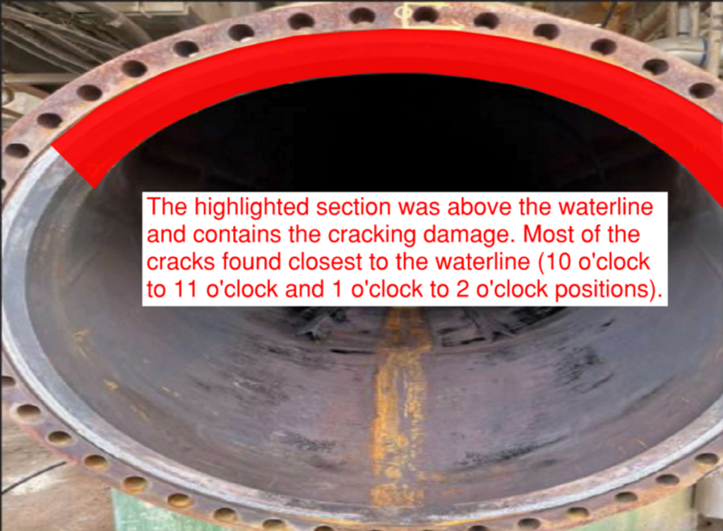
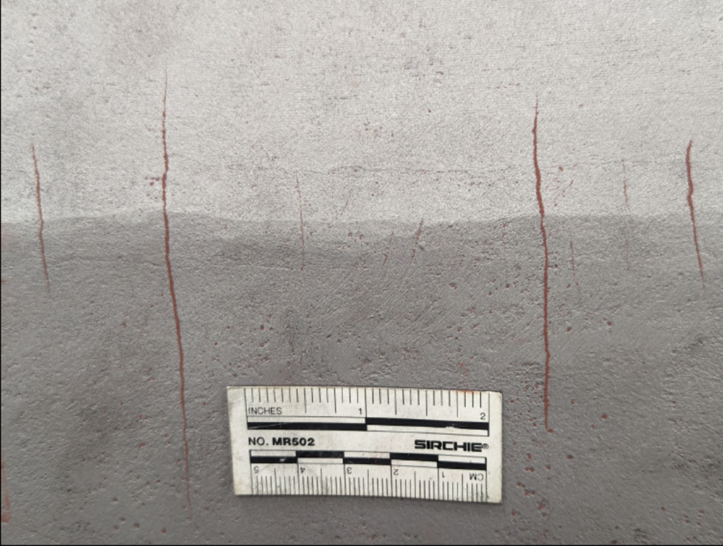
A carbon steel kettle-type exchanger acting as a WHB experienced caustic SCC at the flange-to-cone weld due to low water levels, which concentrated caustic deposits near the waterline (Figures 1 and 2). The intergranular, branching, oxide-filled cracks were consistent with alkaline SCC, such as caustic SCC (Figure 3). The exchanger operated with BFW at around 225 psi and 400°F/204°C on the shell side and vacuum tower bottoms at 650°F/343°C on the channel side. The cracking occurred above the waterline where metal temperatures were highest. To prevent recurrence, it was recommended that water levels should fully submerge the bundle, and regular blowdowns should limit caustic buildup. Also, boiler water should be sampled monthly—and adjusted as needed—for alkalinity, silica, conductivity (ideally measured daily), and pH.
WHB Tube with Galvanic Corrosion
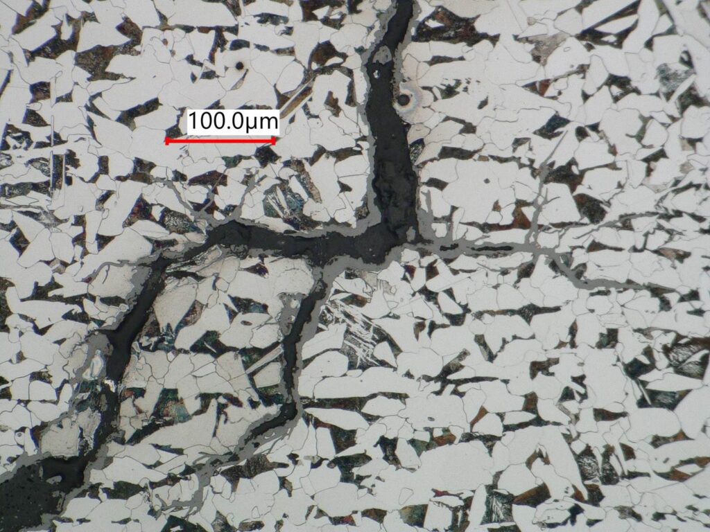
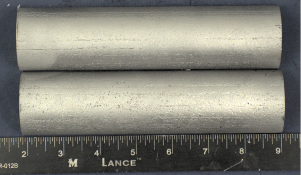
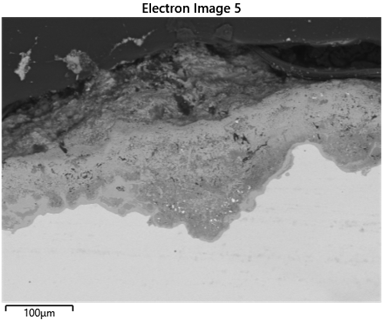
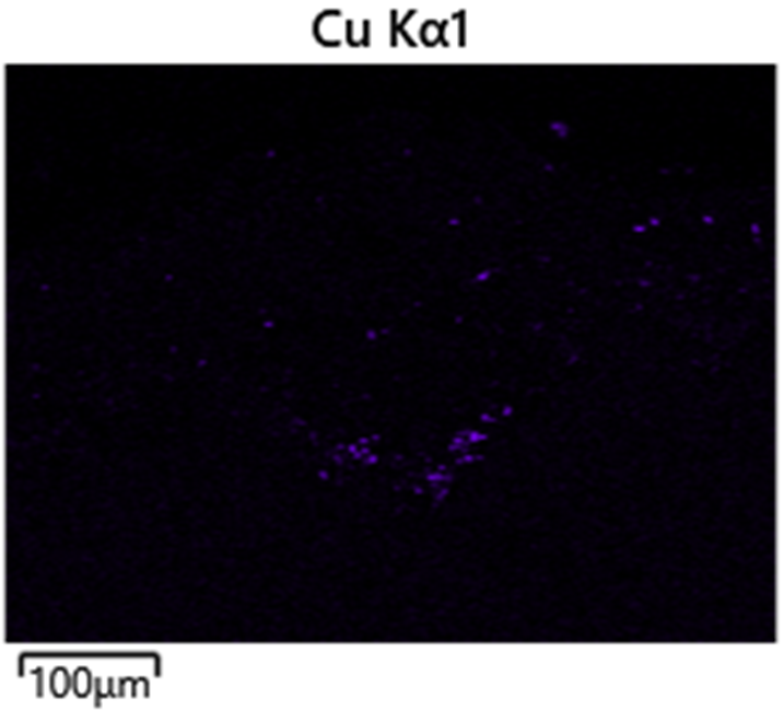
A WHB experienced mild pitting on the water side (outer diameter), likely caused by copper contamination and under-deposit corrosion from acid phosphate or caustic (Figure 4). Metallic copper deposits were found in the pits, indicating contamination from feedwater, possibly due to equipment in the steam system, like surface condensers (Figure 5). Copper contamination can promote localized pitting and scale buildup, leading to either acid phosphate corrosion or caustic gouging beneath excessive deposits. The pitting was not aggressive enough to indicate acid phosphate corrosion, as cross-sections showed no white or pinkish iron-sodium-phosphate deposits typical of acid phosphate corrosion. To prevent similar issues in the future, regular cleaning and blowdowns were recommended to manage deposit buildup and maintain optimal heat transfer surfaces.
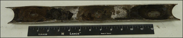
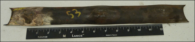
Short-Term Overheat Failure of Boiler Tubes from Severe Fouling
Fouling in boiler tubes led to stress rupture and short-term overheating. The internal fouling reduced heat transfer efficiency and caused local hot spots, resulting in bulges (Figures 6 and 7). Wall loss (likely from oxidation) occurred alongside tensile deformation, and some oxide cracking (5-10 mils/0.13-0.25 mm deep) was observed. The investigation found that an upstream water softener leaked resin beads (polymer-based) into the boiler which decomposed into a coke-like foulant, leading to a lack of heat transfer, increased metal temperatures, and local short-term overheating of tubes. It was recommended to increase the sampling frequency on the feedwater and test for total organic carbon, as well as perform regular blowdown cycles (with sampling dissolved or suspended species).
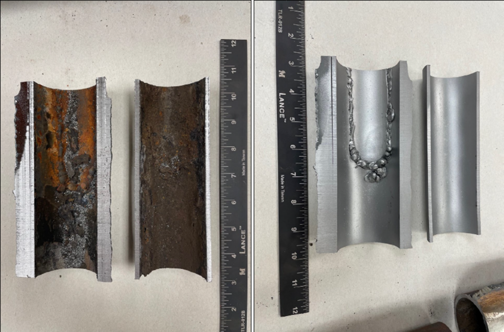
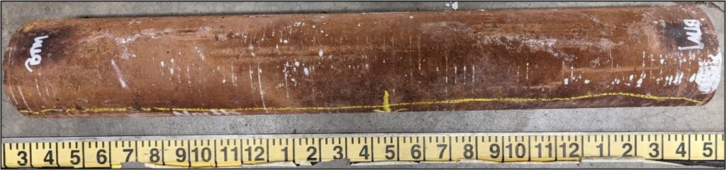
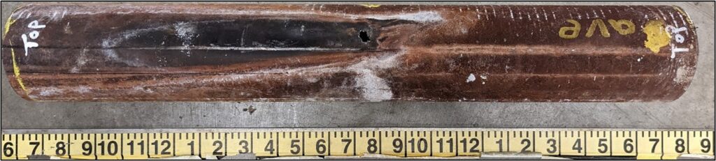
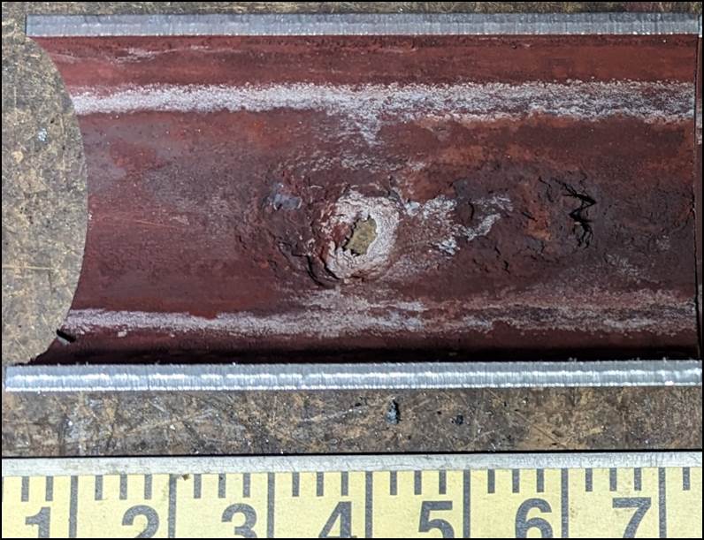
Caustic Gouging Failure of a Convection Section Heater Tube
A combination of partial liquid levels (vapor pockets) and excess free caustic caused a tube in the convection section of a heater to experience failure from caustic gouging. Lines of deposits corresponding to partial liquid levels were identified along the length of the tube sample. The through-wall failure location was located at the top of the tube in the vapor space region of the partially filled tube (Figures 8 and 9). Because they may not be continually submerged in water, the vapor space and “splash zone” regions are prone to scale deposition and under-deposit corrosion. Sodium was confirmed in high quantities at the leak location via SEM-EDS analysis. This was particularly interesting since the treatment program was “all-volatile” (i.e., caustic was not used for pH adjustment); it was suspected that the sodium was coming from softening or inadequate demineralization, combining under the deposits in the tube at high alkalinity (amine-treated feedwater) to generate free caustic.
Conclusion
Boilers and other steam-generating equipment items are prone to a range of damage mechanisms. Preventing failures (and analyzing failures when they do occur) requires a team that understands these mechanisms thoroughly and is well-versed in steam-generating equipment design, monitoring, and operation—including the intricacies of BFW treatment. Reach out to our materials and corrosion experts today for more information or for consultation on your facility’s boilers.
Please submit the form below with any questions for the authors: