An Instrumentation and Control (I&C) system consists of process connections, instruments, cables, conduit, logic solvers, and programming elements, functioning continuously under stringent operational demands. When healthy and working in harmony, these pieces of equipment ensure safe and reliable operations, product quality, customer satisfaction, and optimal production capability. These components must function reliably 24/7/365 with their only scheduled time off being a plant turnaround. This article outlines the best practices for ensuring the reliability and maintenance of I&C systems.
Understanding Reliability and Maintenance
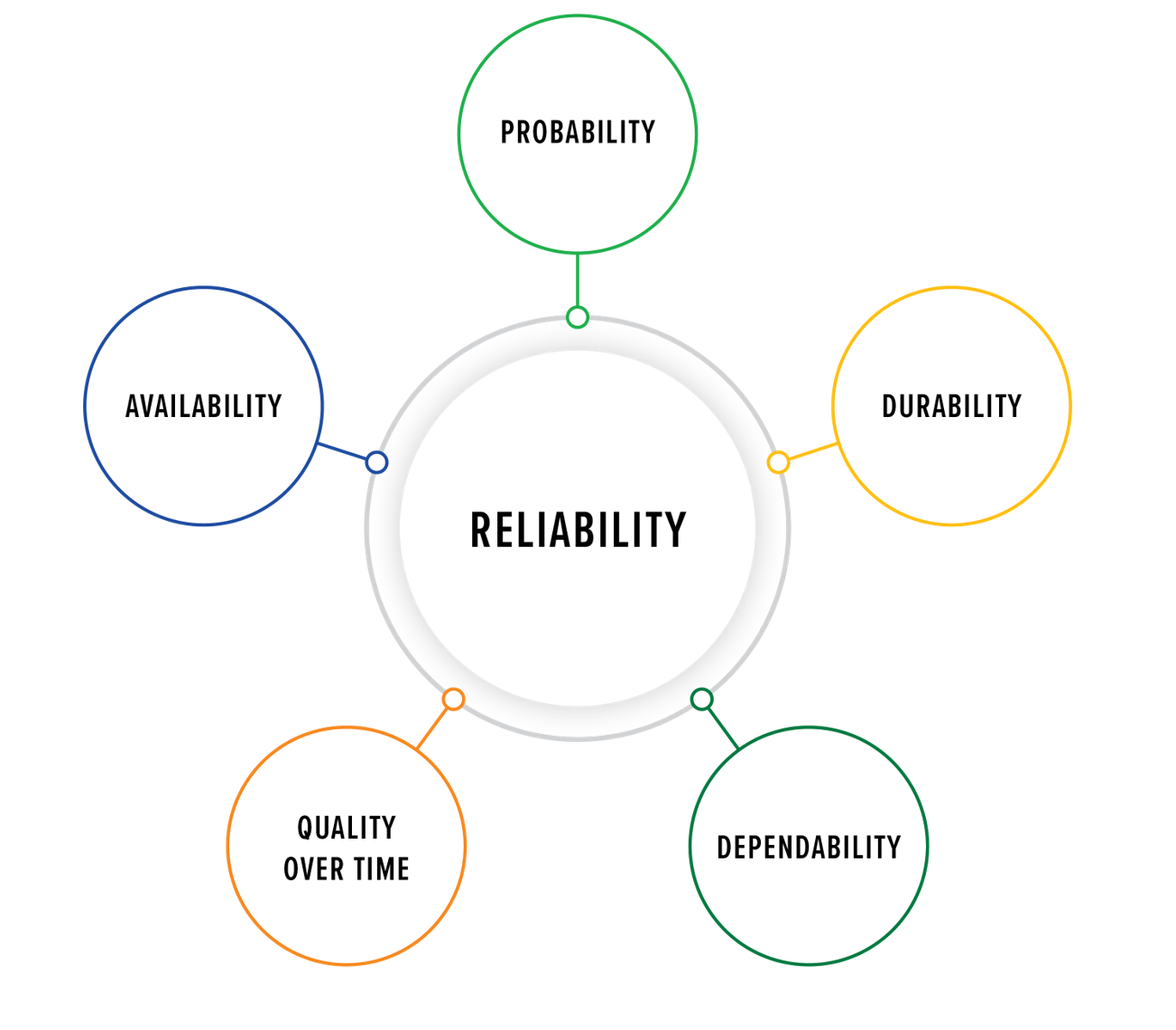
For instrumentation, reliability refers to the consistency of a measuring device in producing the same results under similar conditions, making it a critical factor in process control. Reliability indicates how dependable and trustworthy the instrument is in providing accurate readings over repeated trials. A reliable instrument will yield similar results each time it is used to measure the same process variable, over multiple times.
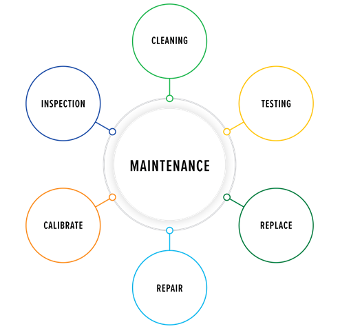
Maintenance is the process. It encompasses inspection, cleaning, calibration, repair, or replacement of system components to prevent failures, safety hazards, and costly breakdowns.
Given the importance of these systems, regulatory frameworks such as OSHA 1910.119 outline 14 essential elements (Figure 3) to ensure safety and operational integrity. Instrumentation is included in the mechanical integrity (MI) element, as it is not just fixed equipment, piping, or machinery.
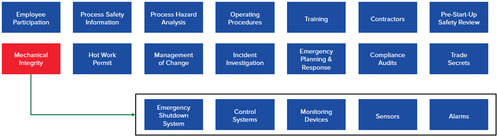
The integrity of process equipment and process controls must be maintained to prevent a loss of containment. This applies to pressure vessels and storage tanks, rotating equipment, piping systems, relief and vent systems, emergency shutdown systems, as well as controls including monitoring devices, sensors, alarms, and interlocks. The OSHA regulation requires written procedures to maintain the ongoing integrity of the equipment and training for all employees involved in that maintenance. Inspection and testing must be performed, and records must be kept. If the inspections or tests reveal deficiencies, then the deficiencies must be corrected in a safe and timely manner. Quality assurance is required for new construction to ensure the equipment is suitable for the service it will be placed in and installed correctly per the design specifications and drawings. In addition, maintenance materials and spare parts must conform and be accepted for intended use.
The emergency shutdown systems and interlocks that are expected to maintain the integrity of the process also need to be tested and inspected. A special subset of emergency shutdown systems and interlocks is safety instrumented systems (SIS). Although not required by OSHA 1910.119, ANSI/ISA 61511 is the recognized and generally accepted good engineering practice (RAGAGEP) for safety instrumented systems in the USA. Normally, the safety instrumented functions that are part of SIS are identified in a hazard and operability study (HAZOP) or other hazard analysis. An example of a safety instrumented function, as a single function, is stopping the flow of fuel gas to a fired heater when the fuel gas pressure at the burners gets too high. ANSI/ISA 61511 requires operations, maintenance, testing (including test interval), and instrument replacement details for each safety instrumented function to be documented in a safety requirement specification (SRS).
Reliability-Centered Maintenance (RCM)
Reliability-centered maintenance (RCM) is a structured approach to maintenance that focuses on optimizing system performance while minimizing downtime and costs. The Society of Automotive Engineers (SAE) has established standards such as JA1011 and JA1012, providing guidelines for implementing RCM programs.
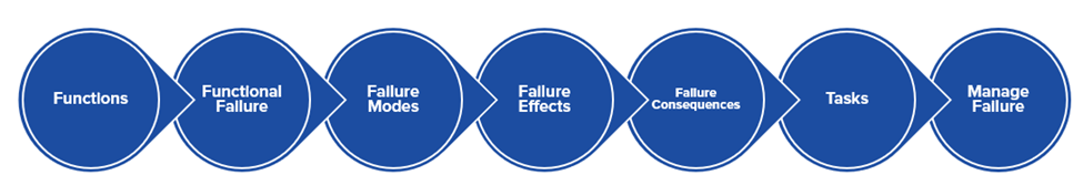
These two standards provide the steps listed for establishing an RCM program.
- Identify the functions and performance expectations of the instrumentation system, including what each instrument should do and how well it should perform.
- Establish how the instrumentation system can fail so it will not provide the desired level of performance.
- Define the causes of each failure that prevent the instrumentation system from meeting the desired level of performance.
- Determine what happens when each failure occurs. For an instrumentation system, this means evaluating how each identified failure impacts the process or associated equipment’s intended performance.
- Classify the consequences of failure (COFs). Analyze each failure that hinders performance and determine its ultimate consequence.
- Identify how to predict or prevent each failure. This means establishing the necessary actions to predict or prevent failures that impede the instrument’s performance.
- Determine if failures can be managed more effectively by modifying the instrument or installation, rather than relying solely on maintenance practices for prevention or prediction.
Standard vs. Practical RCM Approaches
SAE Standard Approach
SAE standard-based approach emphasizes analyzing assets in terms of function, failure, cause, effect, and consequence, treating all instruments equally. A pre-determined, standardized approach to equipment maintenance involves calibration, lubrication, cleaning, and inspections performed on a fixed schedule, regardless of asset criticality or condition. This “one-size-fits-all” strategy often overlooks the needs of critical and non-critical systems and limits task adaptability despite variations in asset performance or changing conditions. The standardized approach is focused on preventative maintenance and does not account for actual asset conditions, which often leads to unnecessary maintenance of non-critical assets, thus wasting resources. While this approach has a lower upfront cost due to its simplicity, it can become more expensive over time due to unplanned failures, over-maintenance, or under-maintenance. Additionally, it tends to be reactive, often failing to address the potential consequences of poorly maintained critical assets. For example, all pressure sensors in a plant may be inspected or calibrated on a fixed schedule, regardless of their criticality or operational condition, potentially leading to inefficiencies.
Practical Approach
A practical approach focuses on instruments with significant safety, environmental, or commercial impact, prioritizing consequence-based maintenance. It optimizes equipment and system maintenance by balancing cost, safety, and reliability. It prevents failures by tailoring strategies based on the criticality of each component and prioritizing assets according to their significance in operations, safety, and compliance. By leveraging risk management, this approach determines whether to maintain, monitor, or allow certain assets to fail strategically. Using condition-monitoring tools and predictive maintenance techniques helps minimize unnecessary maintenance while improving overall system efficiency. Although this practical approach requires an initial investment in analysis and setup, such as Failure Modes and Effects Analysis (FMEA) and advanced monitoring technologies, it is proven to be more cost-effective by reducing downtime, unplanned failures, and excessive maintenance efforts.
Failure Classifications
Evident Failures
Evident failures, also known as overt failures, are self-revealing and the focus of the RCM process. The goal is to identify instruments that, if they fail, cause a consequence of concern that is immediate or will occur in a short period of time. To prevent the consequence of concern, an instrument maintenance strategy is applied to the instrument that is reasonably expected to keep the instrument from failing while in service.
Hidden Failures
Hidden failures, also known as covert or dormant failures, cannot be ignored and are not self-revealing. These failures do not cause a consequence of concern but may significantly increase the chance of a consequence of concern occurring if there is another failure that places a demand on a given instrument’s function. For most if not all hidden failures, the goal is to prevent an undesirable event or alert Operations to the process reaching an undesirable state. If instrumentation has failed, the design intent will not be performed. The emphasis on hidden failures in the instrument RCM process depends on the severity of the consequences when a failed instrument is needed. Instruments that have been identified as a layer of protection are of particular concern, as a hazard analysis has determined they help reduce the level of risk to an acceptable level of a consequence of concern. They are there to prevent a “bad day.”
Risk Assessment
A structured risk assessment process helps organizations determine maintenance priorities. Below are the steps to perform a risk assessment.
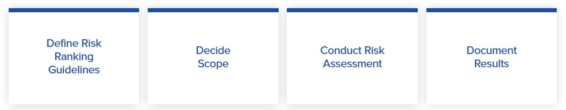
Define Risk-Ranking Guidelines
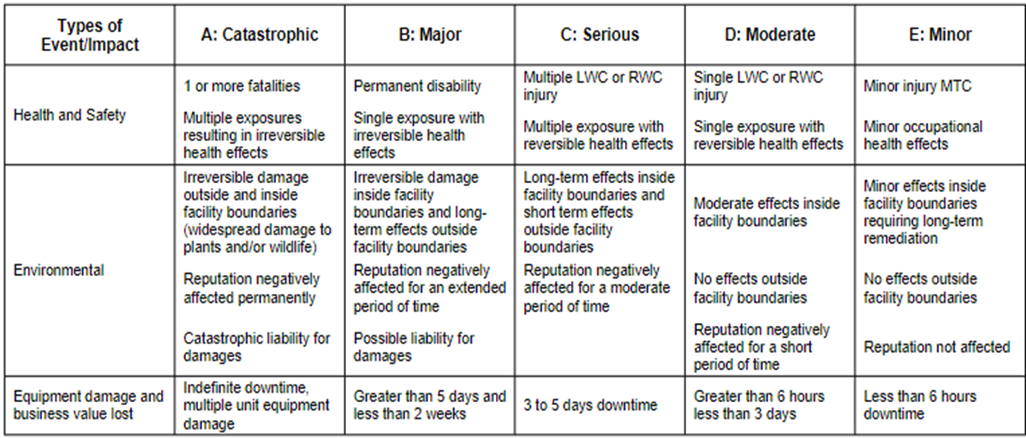
The high-level concept of instrument risk ranking is to determine which instruments are most important to the business and have the biggest impact if they fail to perform properly. Typically, at least three of the instrumentation categories are safety, environmental, and commercial, though there may be others that must be established according to what is important to your company.
After establishing these categories, the granularity or levels need to be established so that the consequence of an instrument failing can not only be categorized, but the appropriate level of the seriousness of the consequence determined.
Determine Assessment Scope
The physical scope of the risk assessment must be determined. Will the instrument risk ranking be performed for an entire facility, including multiple units? Will it cover only certain units or just a single unit within the facility? Also, will the scope include utilities and other outside battery limit (OSBL) areas, or will these be omitted? Will only a portion of the utilities or other OSBL areas be included that are considered higher risk? For example, natural gas and oxygen might be included while nitrogen and cooling water are omitted.
Next, the instrument boundaries must also be defined. Will every instrument be included, or will “standalone” instruments like pressure and temperature gauges be omitted? Will the scope include only those instruments connected to the unit process control system like a DCS or PLC? If so, are there local controls that may communicate with the unit process control system but are controlling a specific piece of equipment? Examples include a local compressor control panel and local dryer controls. Will the instruments connected to these systems be included in the scope or omitted?
The final scope decision is, if previously performed hazard analyses included the in-scope instruments, will these hazard analyses be considered in the risk-ranking analysis? These could be process safety management-driven analyses such as a HAZOP or process hazard analysis (PHA), or risk assessments performed for equipment other than instruments such as fixed equipment, machinery, or fired equipment. It is recommended to use these analyses because a category or level has already been assigned to the instrument or associated equipment. In other words, that part of the risk ranking may already be done for you.
Conduct Risk Assessment
The next step is conducting the risk assessment. Although perhaps obvious, a schedule must be set and meeting invitations sent to appropriate personnel.
The core team who should always be present during the instrument risk-ranking assessment are an instrument engineer, an Operations representative familiar with the operating area being assessed, and an Instrument Maintenance representative familiar with the instruments to be assessed. If the scope is large, the personnel may change with the part of the overall scope being assessed. For example, if the risk ranking is for multiple units within a facility, all three core members may change from unit to unit. It may be helpful to call in subject matter experts when instruments associated with a particular piece of equipment or part of the process are being assessed. If instruments on large machinery are within the scope, a subject matter expert on the machines can help answer questions on the criticality of the machine and the instrumentation function. The same applies to fired equipment and specialized process equipment such as reactors.
Instruments may have been installed to prevent an undesirable consequence but were not identified in a hazard analysis as providing risk reduction required to meet the company’s tolerance for risk. These instruments provide “apparent” risk reduction. Normally, these are instruments that activate a shutdown or an alarm. Although a malfunction of these instruments may not cause a consequence of concern, some of them may cause a spurious (or unnecessary) shutdown of a piece of equipment or part of the process. Typically, spurious shutdowns of major equipment are very disruptive to the process and may cause an environmental or commercial cause of concern. If so, those consequences of concern should be identified while performing the instrument risk ranking. Even if the equipment does not have a significant impact on safety or environment, there may be a large commercial consequence due to the repair cost and process downtime if the equipment is damaged.
There are several types of equipment where instruments providing “apparent risk reduction” might be found, such as fired equipment like fired heaters, boilers, furnaces, and incinerators. They may be equipped with flame detectors; fuel gas pressure (high and/or low); process flow; the status of forced or induced draft fans or combustion air flow; firebox pressure; stack and process exit temperatures; and, for boilers, level and pressure. A hazard analysis may assign risk reduction to one or more of these protective functions, but not all. Does that mean the ones not assigned risk reduction should be ignored? No. The USA PSM regulations require that shutdowns and interlocks be included in an MI program.
For example, consider a fired heater that is equipped with flame detectors, fuel gas pressure, process flow, and firebox pressure shutdowns. A hazard analysis assigns risk reduction to the flame detectors, assuming that as long as a flame is present, the heater remains in a safe state, but it does not assign risk reduction to the other three protective functions. Does that mean the other three protective functions can be ignored? No. They have been installed to protect against a specific condition that could lead to an undesirable event and should work. While instruments not assigned risk reduction may not require the same level of focus and rigor as those that have, a maintenance strategy should still be in place to ensure proper function. From a risk perspective, instruments that contribute to apparent risk reduction should be categorized at the same level as those officially assigned risk reduction for the same equipment, hazard, and potential consequence. For the fired heater, this might be firebox explosion and the resulting safety consequence.
For environmental consequences, there may be instruments that are important to prevent damage to the environment even though they are not subject to an environmental regulation. Types of instruments typically perform the following: indicate the opening of atmospheric relief valve in hydrocarbon service, measure flow to a flare, measure flow associated with greenhouse gas, provide an analysis of water contaminants for water that will be released back into the environment typically found in wastewater treating, and measure NOx emissions from fired equipment.
Commercial considerations are normally obvious as instrument failure will or can (in the case of hidden failures) have a significant negative impact on business performance because the result will be process downtime, repair cost for damaged equipment, and possibly degradation of customer confidence from unfulfilled contractual agreements. Many times, there is a large overlap with safety-related instruments as they’re designed to protect both personnel and equipment from damage. Safety is a key consideration for fired equipment, large compressors and pumps, and reactors. Damage to these systems will be costly to repair and cause significant process downtime, in addition to being an immediate safety hazard to personnel.
Instruments that may be less obvious candidates for risk assessment are quality-related instruments like mass spectrometers, gas chromatographs, custody transfer, or other specialty analyzers that measure quality of a product. If the custody transfer instruments are not accurately measuring the quantity of product, the commercial consequences can be quite high. Finally, third-party one-off controls are often overlooked and may have proprietary controls or other unique instruments that are rarely spared. If this equipment fails and is critical to the process, the commercial impact of the failure and time-consuming and/or expensive repairs must be considered.
Document Results
Documentation of the instrument risk-ranking results, including bad actors, in an easily maintainable system is important, as the data is considered “evergreen” and is expected to change with updated hazard analyses, process changes, and continuous improvement. You may use any system you choose, such as a spreadsheet, or database software such as Microsoft Access, or a Computerized Maintenance Management System (CMMS) if it has provision for it.

In the above example, the first instrument, a temperature transmitter, does not have any significant consequences if it fails. The second instrument, the flow transmitter, is a low flow shutdown for the charge heater and has been credited with risk reduction in the last HAZOP. Likewise, the third instrument is differential pressure across a slide valve, and it was also assigned risk reduction in the last HAZOP. These instruments have a relatively high risk associated with their failure. The fourth and final instrument, a lube oil pressure transmitter on the unit air compressor, was not credited with risk reduction in the last HAZOP, but it does have apparent risk reduction because it is a low lube oil pressure shutdown for the unit air compressor.
Instrument Maintenance Strategies
The example below is a matrix that can be used to indicate what instruments will initially receive maintenance strategies after performing the instrument risk-ranking assessment.
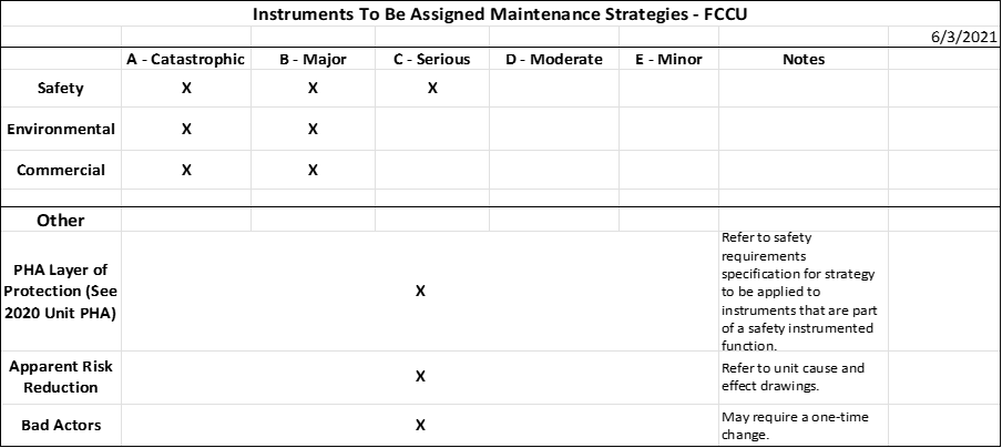
In this example, for safety, instruments whose failure results in or can lead to a catastrophic, major, or serious consequence will be assigned maintenance strategies. These instruments may also be involved in a layer of protection in the last PHA, or may provide apparent risk reduction. Instruments can appear in multiple categories when determining maintenance strategies, as the result remains the same and a maintenance strategy will be applied. For environmental and commercial risks, maintenance strategies will be applied to instruments whose failure may lead to catastrophic or major consequences. In addition to the risk ranking, maintenance strategies will be applied to instruments that have been credited with risk reduction in a PHA, those with apparent risk reduction, and to bad actors. Use the SRS when establishing the maintenance strategies for instruments that are part of a safety instrumented function per the last PHA. The unit cause-and-effect drawings determine instruments that provide apparent risk reduction for maintenance strategies. For bad actors, it is noted that a one-time change may be required versus only establishing a maintenance strategy.
Effective Maintenance Strategies – Basic to Advanced Approaches
The most basic maintenance strategy is corrective or run-to-repair. The next level is preventative, based on a defined schedule, while the most advanced strategy is predictive or condition-based. A fourth strategy is a one-time change to improve the performance of an instrument or associated controls. The concepts of preventative, predictive, and one-time changes are part of the RCM standard, and the standard’s last two steps determine how to predict or prevent each failure and whether failures may instead be effectively managed with a one-time change.
Corrective Maintenance
Corrective maintenance, also known as “run to repair,” is the most basic maintenance strategy. This reactive approach is applied when failures have a minimal operational impact and is often the default strategy for instruments not assigned another preventative or predictive maintenance strategy. With this strategy, an instrument is installed and commissioned, and then nothing else is done to it unless it affects operations to the extent that maintenance is requested to repair it. Typically, this involves Operations entering a work order into the CMMS for maintenance to determine why the instrument is not functioning as desired. This is a legitimate strategy for instruments whose failure will not significantly impact business goals per the established criteria used in the risk-ranking assessment and that are not bad actors.
Preventative Maintenance
A more advanced strategy is preventative maintenance, which uses scheduled interventions (replacement or overhaul) based on historical data, manufacturer recommendations, and regulatory requirements. Although the instrument can still fail in between preventative maintenance activities, the intent is to lower the probability to an acceptable level. A preventative maintenance strategy will ensure an instrument never reaches “end of life” provided the scheduled maintenance is within the useful life and restores the instrument to “like new” condition. This strategy can also be used for repetitive tasks like calibration or function checks that are not intended to restore the instrument, but to ensure it is functioning properly.
Schedule Consideration – Preventative Maintenance
The preventative maintenance intervals are based on data extracted from the CMMS if there are enough of the same instrument types in similar service and enough failures to justify the maintenance interval. The instrument manufacturer’s recommended maintenance schedule can be followed; however, this schedule rarely recognizes the service conditions of the installation. If there is no or little data available (e.g., new instruments or where there is a small number in service), the manufacturer’s recommended maintenance schedule may be the only guide available. The instrument maintenance staff can provide valuable input, but always check available data to confirm or contradict personal recollections.
Instrument preventative maintenance activities are typically included in major maintenance events such as turnarounds or other outages. If not essential, avoid scheduling preventative maintenance activities outside the scope of the outage. Some instrument preventative maintenance activities must be scheduled to coincide with other disciplines like machinery, fired equipment, or catalyst replacement in a reactor. For example, if machinery maintenance will have a reciprocating compressor out of service for head retorque every three years, even if the data shows that the instrument maintenance associated with the compressor only needs to be done every four years, the instrument maintenance schedule must be adjusted to every three years to coincide with the mechanical work if the instrument work cannot be done with the compressor in service.
Some maintenance intervals (or schedules) are set by regulation or industry standard, and there is little to no flexibility. These include intervals set by environmental regulations, instruments that are part of a safety instrumented function with associated safety requirements specification, industry standards for boilers or pressure vessels, or where experience shows that maintenance must be performed at a defined interval to avoid a high likelihood of instrument failure and its associated consequence of concern. In the case of instruments that are part of safety instrumented functions, the preventative maintenance will probably be for testing and not repair or replacement, but it is possible the SRS may require repair or replacement at some given interval.
Predictive Maintenance
As the most advanced instrument maintenance strategy, predictive maintenance uses condition-based monitoring through online diagnostics, non-destructive testing (NDT), and advanced sensor analytics. This strategy requires knowledge of an instrument’s conditions to accurately predict when it will fail; being able to predict when an instrument will fail sufficiently in advance is key to performing maintenance. In this case, accuracy does not mean the exact second or minute, but a window of time in which the failure can reasonably be expected to occur (e.g., an instrument is predicted to fail within two to four weeks from now).
Instrument condition should be determined via continuously available online diagnostics, periodically checking or downloading available instrument health information but not continuously online, NDT that can be done with the process in service, and/or visual inspection.
Online Diagnostics
To provide diagnostics, instruments must be smart and capable of self-diagnosis; in addition, the diagnostics must be continuously available through highway addressable remote transducer (HART) (or other proprietary protocols from an instrument manufacturer) or a bus technology like Foundation Fieldbus or Profibus. The diagnostic data must be gathered by a centralized system, such as a distributed control system, typically with “built-in” asset monitoring software, or the diagnostic data can be stripped from the control signals by modems in marshaling cabinets and then fed into a centralized system with asset monitoring software. The asset monitoring software clearly displays the diagnostic data and presents instrument health without a confusing amount of data. Typically, the end user may customize the dashboard to display diagnostic information with instruments highlighted as red, yellow, or green, corresponding to an immediate concern, a minor or possible concern, and normal instrument function, respectively. A “drill down” option is then available to get more detailed information about the condition of the instrument and any instrument health alerts.
Periodic Checks or Downloads of Instrument Health Information
Another way to obtain diagnostic information is periodically checking or downloading instrument health information, using an instrument that is smart and capable of self-diagnosis. The difference here is that the data is stranded. In other words, it is not being continuously gathered. The data may be available through HART or bus technologies like Foundation Fieldbus and Profibus, or it may come from complex instruments like analyzers, which often have a laptop connection for large volumes of diagnostic data. Since the data is not being continuously gathered, someone must manually create a task to gather the data. For “normal” process instruments like pressure and temperature transmitters, it would be tedious to gather the instrument data one at a time; consider using this method for a small facility or a limited number of instruments where the data is stranded. For example, if a PLC is incapable of stripping and handling the instrument’s diagnostic data, consider obtaining diagnostic data valve by valve from control valves with smart positioners when control valve diagnostics are stranded. This step is normally done just before or early in the outage to determine a more precise scope of work for the valve and assess whether any maintenance is required. Depending on the required level of diagnostics, it may be necessary to bypass the valve if it is in service. For example, obtaining a valve signature may require bypassing the valve if it cannot be isolated while the process is in service or if operations cannot tolerate the valve completing its signature cycle. For complex instruments with a laptop connection, the diagnostic data can be downloaded for immediate or future use and can be sent to an instrument manufacturer or supplier for off-site analysis, if permitted by your company.
Non-Destructive Testing (NDT)
NDT must be performed with the instrument in service. This is useful for instruments that have no or limited built-in instrument diagnostics. The intelligence, therefore, is in the test equipment and not the instrument. Examples of NDT or contexts in which it is used include:
- X-raying the internals of a valve to determine if there has been significant corrosion or erosion. A Geiger counter can measure the strength or leakage of the source in a nuclear instrument.
- Viewing and analyzing the echo curve of a radar level gauge to periodically check or download instrument health information if the radar diagnostics are stranded.
- Checking the calibration of a transmitter with certified test equipment. If the transmitter is part of a control loop, it must be permissible to manually run the loop while the calibration is checked.
- Performing an automated partial stroke test of a block valve to ensure that it strokes the desired percentage to periodically check instrument health information if the test cannot be performed automatically.
Visual Inspection
Visual inspection is a simple yet valuable method for assessing equipment condition by identifying persistent failures or signs of deterioration, though it provides limited data and may not capture all potential issues. Examples of visual inspections include checking if the magnetic level gauge’s indicator follows the float, ensuring impulse line tubing remains properly sloped without bends, and verifying that no visible damage or misalignment has occurred. Even with limited diagnostic insight, visual inspections offer an early detection of mechanical issues and prevent potential failures.
Alternative Strategies
Persistent failures caused by improper technology selection, installation errors, or ineffective control strategies may require one-time modifications. In such cases, implementing permanent changes is an alternative strategy to consider. Typically, these modifications involve collaboration with other departments, rather than only maintenance team tasks. By definition, any change must adhere to a company’s management of change policy. One-time changes are often the best option to address bad actors and may be the only option if a preventative or predictive maintenance strategy is not practical or possible for instruments that are not bad actors.
Continuous Improvement Through Data Analytics
First, a system must be in place to keep track of instrument assets that also facilitate data mining and possibly data analysis. Typically, plants use a robust CMMS which supports data-driven decision-making. Regardless of where the data is stored, the instrument asset database must contain, at a minimum, the following details:
- Instrument tag number
- Instrument manufacturer
- Instrument model number
- Serial number
- Date the instrument was commissioned or placed in service
- Date the instrument was decommissioned or replaced (in other words, regardless of how many times the instrument has been replaced, a record should be kept of every replacement and duration in service before being replaced)
- Data should be kept where it is easy to determine what data, including work order history, is associated with the in-service instrument at the time
The second consideration for gathering data is the initial entry of maintenance strategies. To mine data associated with maintenance strategies, particularly preventative maintenance strategies, the system must be capable of entering and retaining the following:
- A description, including the basis for the strategy – what is or was supposed to be done to the instrument, why was this maintenance strategy assigned (refer to the instrument risk-ranking assessment), what was the established frequency, and was there any required coordination with other crafts or personnel procuring replacements or spare parts?
- The frequency – what is the interval? Every six months, every year, every five years?
- The date of the initial associated work order will be generated by the system, with frequency setting when the next work order will be generated, and the one after that, etc.
- The due date for completing the maintenance activity – typically means “no later than” but can also refer to a window during which the maintenance activity must be completed between two dates, especially if performing it too early may impact the next due date.
- Required resources – how many technicians are needed, how long the task is projected to take, what materials are required including a replacement instrument or spare parts (e.g., thermally conductive grease or a new gasket, bolts, and nuts), and whether there are any special equipment like a manlift or breathing air needed.
- Finally, the system must be capable of tracking any required coordination, such as performing the work to coincide when a piece of rotating equipment is down for maintenance. Alternatively, there is a system that allows the assignment of a lead craft and then tracks any other crafts that need to perform work simultaneously. Beware of pitfalls in this type of approach. If the lead craft is machinery and they forget to notify the instrument department of the machinery downtime, then the opportunity to perform the work may be lost until the next scheduled outage.
The third consideration for the CMMS must allow one-off work orders to be written for instrument replacement or repair (e.g., instruments with a run to repair strategy, or those with other strategies when they unexpectedly fail). The system must generate work orders from maintenance strategies – primarily preventative maintenance, but could also be the scheduled part of obtaining diagnostic data from an instrument with a predictive maintenance strategy. Although it may seem straightforward for the system to handle both types of work orders, it is crucial that the work order clearly specifies if it was manually written and entered as a one-off or whether it was automatically generated by a maintenance strategy.
The fourth consideration is how to set up the system to accept and retain work order results. The system must accept and retain the as-found and as-left conditions of the instrument, including whether or not the as-found condition was a failure. This establishes instrument failure criteria, enabling instrument maintenance technicians to determine whether the instrument failed or possibly only needed recalibration.
The actions or work performed on the instrument must also be recorded – was a part replaced, was the entire instrument replaced, was the instrument only cleaned and placed back in service, or was nothing done to it? If possible, it may be beneficial to establish a drop-down menu or reference sheet for instrument technicians to choose the most accurate description of the completed task. This allows for easier searches during the data mining step. In addition, technicians need a free form field to provide a thorough description of what work was completed and why the action was taken. Was a part broken or corroded? Was the instrument non-responsive, or could it not be re-calibrated within the required tolerance? Were there deposits on the measuring cell in need of cleaning? Or was there simply no problem found and therefore nothing was done to the instrument? A company may establish its own criteria and set up preconfigured explanations of what was done and why, or leave it up to the technicians.
Furthermore, criteria must be established to determine when a root cause failure analysis (RCFA) is required and which personnel should be involved. The level of involvement can range from technicians to a multi-disciplinary team, depending on the severity and potential consequences of the instrument failure. The system should either track and assign action items related to RCFA or integrate with a separate facility-wide action tracking system. Regardless of the approach, the ability to search and analyze instrument-related RCFAs and their action item status is essential.
Finally, the data analysis results need to provide sufficient information to determine if further action needs to be taken. Periodically reviewing RCFAs, especially for any instruments that are frequently failing or causing downtime, helps supplement general searches done on a larger number of instruments. The data analysis needs to indicate whether an FMEA or the RCM standard approach should be performed for an instrument or group of instruments, if the frequency or increase in failures warrants additional investigation. The data analysis must show if there is insufficient data to determine the root cause or causes of failure, in which case an instrument or group of instruments may need to be returned to the manufacturer to determine or confirm the cause of failure. For example, if there is an excessive number of coil burnouts on a particular model of solenoid over the past two years and the maintenance department does not know why, defective coils may need to be returned to the manufacturer for further investigation. If the maintenance department was discarding the defective coils, they must start retaining them for any future failures and return to the manufacturer.
A one-time change may be considered if the adjusted maintenance strategy does not result in the desired instrument performance, or if the changes negatively impact the practicality and cost-effectiveness of the strategy. An example of a one-time change is choosing a different technology, preferably a technology already proven in the same or similar service at a given facility. A different instrument manufacturer should be considered if there are significant advantages over the current manufacturer, such as enhanced diagnostics or online or off-line redundancy. It may be beneficial to install multiple instruments to measure the same process variable or a standby instrument that can be quickly put in service if the current one fails. The latter would only be possible for instrument failures if a brief outage does not result in a consequence of concern. An alternative control strategy can be considered if the process variable is extremely difficult or impossible to measure.
Role of Artificial Intelligence in Reliability and Maintenance
Artificial intelligence (AI) replicates human intelligence by utilizing two essential components: access to reliable data and machine learning (ML) algorithms. AI-driven solutions continuously monitor operational conditions, comparing them against baseline data to detect anomalies. Even minor drops in efficiency are flagged as early indicators of potential maintenance needs. This proactive approach enables maintenance teams to repair or replace components before they fail, reducing downtime and enhancing system reliability.
Traditional maintenance approaches often rely on reactive strategies, leading to high costs, inefficiencies, and unexpected equipment failures. In contrast, data-driven proactive solutions leverage real-time analytics to enhance reliability, reduce downtime, improve safety, and extend equipment lifespan. A key metric for evaluating maintenance effectiveness is overall equipment effectiveness (OEE), which is calculated as the product of availability, performance, and quality.

By optimizing resource allocation, such as ensuring the availability of spare parts for critical components, organizations can enhance operational efficiency. Furthermore, continuous data collection and feedback enable the refinement of AI algorithms, driving ongoing improvements in asset performance. The integration of Industrial Internet of Things (IIoT) and AI further enhance maintenance strategies by enabling remote asset monitoring and control, facilitating predictive maintenance, and minimizing operational disruptions.
Advancements in AI, sensor technologies, and IIoT connectivity are expected to enhance predictive maintenance capabilities, leading to cost reductions, improved sustainability, and heightened competitiveness in the global market.
Conclusion
Ensuring the reliability and maintenance of I&C systems is vital for industrial safety, efficiency, and profitability. By adopting RCM principles, leveraging AI-driven predictive maintenance, and continuously refining strategies through data analytics, organizations can optimize asset performance and reduce operational risks. As technology evolves, the integration of AI and IIoT will play an increasingly pivotal role in shaping the future of industrial maintenance. The ICE team can assist with risk assessments and developing instrument maintenance strategies. Contact ICE team members for support with I&C systems reliability and maintenance challenges.
Please submit the form below with any questions for the author: