The Occupational Safety and Health Administration (OSHA) requires owner-users to maintain essential documentation authenticating adequate design and maintenance of pressure vessels and storage tanks. Unfortunately, it is not uncommon to find equipment operating in industry with minimal or no documentation. Suitability-for-service (SFS) is the process of performing inspection and engineering to obtain OSHA compliance for fixed equipment lacking documentation. API 510 [1] Section 7.7, Evaluation of Existing Equipment with Minimal Documentation, is recognized by OSHA interpretations for OSHA 1910.119 as the acceptable means to determine equipment SFS.
If numerous equipment items requiring SFS exist at a particular facility, it is beneficial to complete all the evaluations together as a single “large-scale” project in order to expedite results; ensure consistency of methodologies, procedures, and assumptions; and minimize cost by taking advantage of the efficiencies gained through focused inspection and engineering personnel assigned to the project. A large-scale project typically involves at least 20 pieces of equipment and common deadlines or milestones. Large-scale projects can also present a number of challenges. Experienced project management, regular communication, and clearly defined procedures and actions are required. For large-scale projects, E2G typically develops a project protocol document to ensure consistency by defining the workflow with clear roles and responsibilities, specifying project communication and status updates, and documenting the evaluation methodology and assumptions.
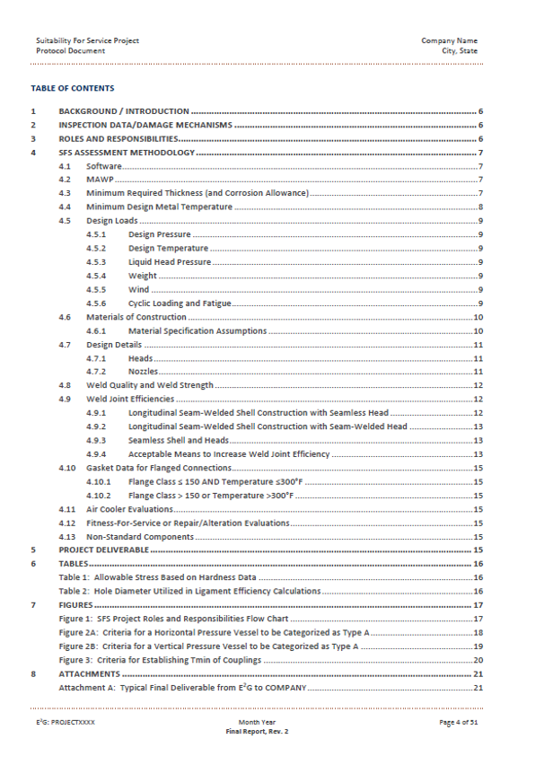
A project protocol document for a large-scale SFS project is a document that encompasses all relevant information regarding the assessment – except the results of the individual analyses for each piece of equipment – and defines the procedural scope of the project. Development of the protocol document is critical to the success of a large-scale SFS project and should be the project’s first task. The following are recommended components in a protocol document:
- Documented process workflow/flowchart
- Roles and responsibilities for various parties involved (e.g., inspection, owner-user, analysts)
- Field data collection sheets
- Technical methodology and procedures
- Engineering assumptions
- Template for consistent presentation and documentation of results
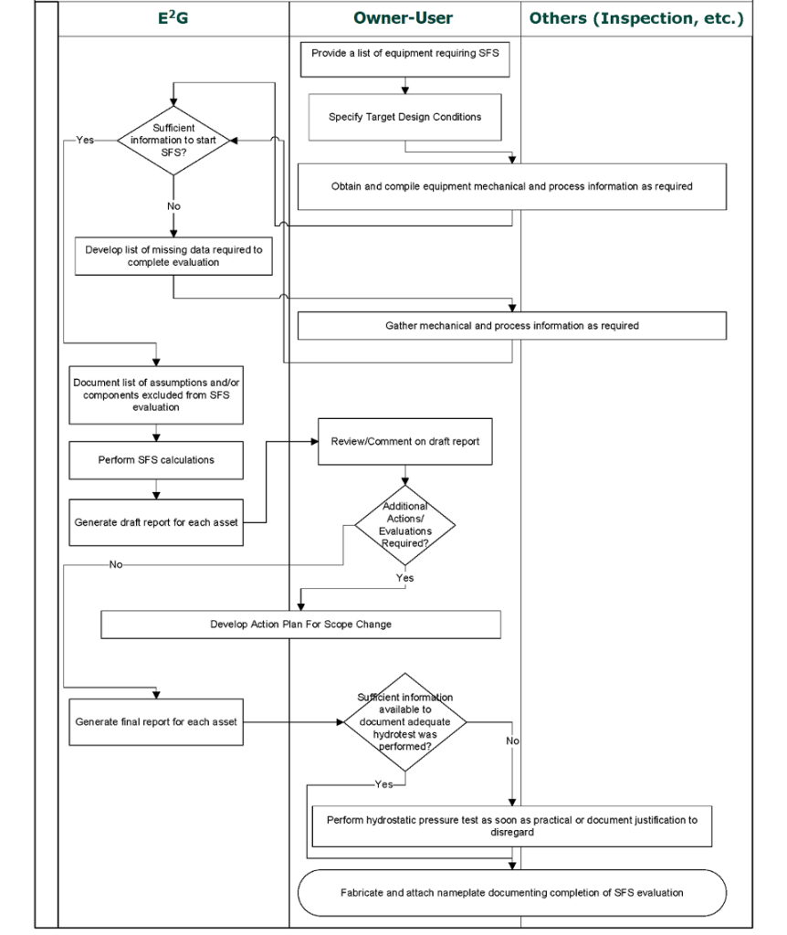
The general SFS process is as follows:
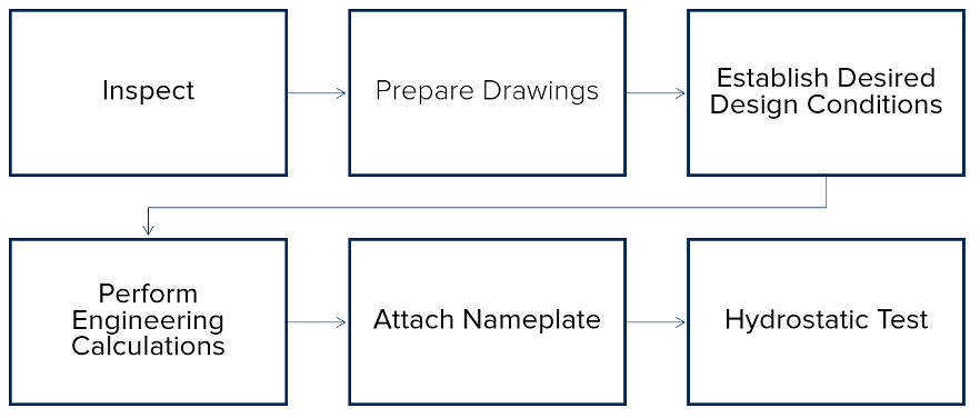
For a large-scale SFS project, the SFS workflow is included in the project protocol document. Typically, a flowchart is included in the project protocol document to visually show the project process. Details such as kick-off meetings, check-in meetings, and reviews are also included in the project-specific workflow. To allow for consistent and transparent equipment and status tracking, E2G commonly uses an electronic workflow management system. This system allows all parties involved in the project to have access to live updates on status, open action items, and final disposition for each equipment evaluation. Additionally, it allows for electronic tracking of the project workflow (waiting on data, ready for analysis, ready for review, draft issued, issued as final).
Roles and responsibilities are defined in a large-scale SFS project protocol document and apply to both E2G and the owner-user. Roles and responsibilities such as project management, analysis, reviews, and professional engineer acceptance and stamping of results are typically the responsibility of E2G, while roles and responsibilities such as establishing equipment items to include in the project along with the desired design conditions, data collection, field inspections, and nameplate attachment are typically the responsibility of the owner-user.
E2G has created a library of field data collection sheets covering an array of equipment items such as vertical vessels, horizontal vessels, heat exchangers, air coolers, and tanks, as well as a variety of components such as shells, nozzles, and flanges, to aid in the inspection step of an SFS evaluation. The field data collection sheets highlight the information needed for SFS evaluations and can streamline the inspection process.
Download the Field Data Collection Sheet for Horizontal Vessels
The large-scale SFS project protocol document also details the technical methodology and procedures used in the SFS evaluations and states engineering assumptions that may be required in SFS evaluations. Capturing the technical methodology and engineering assumptions in one document ensures consistency across all equipment items included in a large-scale SFS project. Design conditions such as maximum internal pressure, maximum external pressure, maximum temperature, minimum temperature, and operating conditions are typically defined in the SFS project protocol document. Calculation methodology and assumptions such as loading (e.g., pressure, weight, wind, seismic, etc.), material properties, weld joint efficiency, and inclusion of an appropriate future corrosion allowance (FCA) are also specified in the SFS project protocol document. Because equipment items requiring SFS evaluations are missing some or all design documentation or records, engineering assumptions for any missing information are included in the SFS project protocol document.
Finally, a large-scale SFS project protocol document defines the template for consistent presentation and documentation of results. In addition to the SFS project protocol document, individual equipment summary reports are created for each equipment item evaluated in the large-scale SFS project. The individual equipment summary reports are defined in the large-scale SFS project protocol document, and a template for these reports is included in the project protocol document. Other deliverables for a large-scale SFS project could include generation of equipment drawings, data sheets (similar to Form U-1A), and SFS nameplate creation. Additionally, a fully populated SagePlus™ software database for all equipment items included in the SFS project can be provided as a deliverable to facilitate future mechanical integrity management in the event a rerate, repair, alteration, or fitness-for-service (FFS) evaluation becomes necessary. All large-scale SFS project deliverables will be defined and specified in the protocol document.
CASE STUDY EXAMPLE
The following case study is provided to illustrate the benefits of establishing a protocol document for large-scale SFS projects. In this case, E2G was contracted to perform SFS evaluations on 67 equipment items lacking full documentation. The equipment items to be evaluated ranged in vintage from the early 1940s through the 1970s, with varying degrees of documentation available. Some had OEM fabrication drawings, nameplates, and/or code stamps directly applied to the vessel. Others had no original documentation whatsoever.
The SFS protocol document developed for the project in consultation with the client established the roles and responsibilities as described in the figure below:
The work scope was reduced as much as possible by identifying identical or nearly identical equipment items and evaluating those items using a single set of calculations where possible, using worst-case measured thicknesses for each component to establish retirement thicknesses and available FCAs.
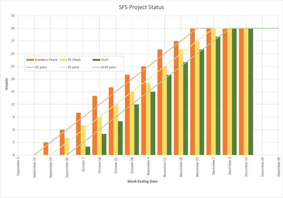
At the client’s request, the project was conducted in phases (this is not uncommon for large-scale SFS projects), with evaluations of the first phase vessels being conducted while data gathering commenced for the next phase, and so on.
The plot below shows E2G’s internal tracking of one of the phases of the case study SFS project. Each vessel assessment reaches the stage at which initial calculations are completed and ready for a numbers check, followed by Responsible Charge review by a Professional Engineer (P.E. or P.Eng.) registered in the state or province in which the equipment resides, through issuance of a draft report to the client for review.
Assessment Methodology:
The baseline procedure for performing the SFS calculations was in accordance with item 3 in Section 7.7 of API 510 [1], Evaluation of Existing Equipment with Minimal Documentation. For items not specifically discussed in API 510, the protocol document was used to establish the specific methodology to be employed.
E2G’s proprietary SagePlus™ software was used to perform the ASME Boiler & Pressure Vessel Code, Section VIII Division 1 (ASME VIII-1) calculations covering the majority of components evaluated in the SFS project.
Design loading for each assessment included design pressure, design temperature, and liquid head pressure. The effects of weight and wind were also included in the assessment for vessels that did not qualify as Type A components per API 579, and cyclic loading was considered on a case-by-case basis.
A global FCA was established for each equipment item based on the limiting pressure boundary component and was then applied to all remaining components to calculate individual component maximum allowable working pressure (MAWP) values. Structural minimum thicknesses were established for various components in the protocol document; these values were sometimes limiting in lieu of thicknesses required for internal or external pressure or nozzle reinforcement for certain components.
For each equipment item, a minimum design metal temperature (MDMT) was also calculated for each component, using the global FCA established for the vessel. Component MDMT values could be much higher if each component were to be evaluated at its individual retirement thickness.
Materials of Construction:
Where vessel drawings or nameplate data regarding year of construction, materials of construction, or material allowable stress were available, that data was used in the calculations. For vessels with nameplates that indicated the year of construction and included a code stamp, but which did not explicitly indicate the material of construction, the minimum allowable stress material permitted for the applicable plate thickness per the original code of construction was used in the calculations (see Figure A). Where this data was not available, the following assumptions were made:
| Year of Construction | 1965 (assumed) |
| Carbon Steel Material: | |
| ⚬ Plate: | SA-283 Grade C |
| ⚬ Welded Pipe: | SA-53W Grade B |
| ⚬ Seamless Pipe: | SA-53 Grade B |
| ⚬ Forgings: | SA-105 |
| ⚬ Castings | SA-216 Grade WCB (casting quality factor of 0.8 per UG-24(a)(1)) |
For alloy and nonferrous materials, X-ray fluorescence analysis was used by the owner-user to determine material type and, thus, allowable stress values.
In accordance with Annex F of API 579, the baseline assumptions for material allowable stress may be increased using hardness testing. Every plate/pipe of each pressure-retaining component for which a higher allowable stress value is desired must be hardness tested. For equipment items or specific components that did not achieve acceptable results using the baseline material assumptions noted above, hardness testing was sometimes used to reduce conservatism in the material properties used in the assessment.
Unless specified otherwise, bolting for equipment girth flanges was assumed to be SA-193-B7 material.

Weld Joint Efficiencies:
Where a vessel drawing or a nameplate attached to the vessel explicitly stated the weld joint efficiencies or level of radiography and post-weld heat treatment, those values were used in the calculations. For vessels with nameplates that indicated the year of construction and included a code stamp with radiography and/or post-weld heat treatment markings, the meaning of those markings per the original code of construction was applied in determining the joint efficiency to be used in the calculations.
API 510 mandates that when the vessel weld joint efficiency is not indicated on a drawing or nameplate and the extent of radiography is unknown, a joint efficiency factor of 0.7 shall be used for butt welds. This correlates to a single-sided longitudinal weld without a backing strip per ASME VIII-1, Table UW-12, Weld Type (1). For the case study SFS project, specific criteria were used to establish the weld joint efficiency to be used for each component depending on year of construction, extent of radiography, and whether components were seamless. One example weld joint efficiency map is shown below:
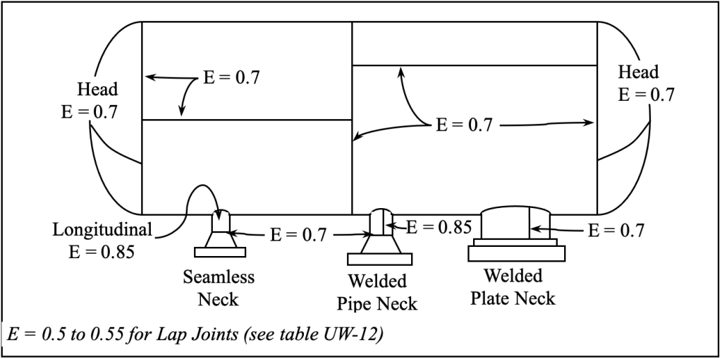
E2G has access to and experience with numerous legacy codes and standards to provide this type of guidance regarding materials of construction and weld joint efficiencies for SFS projects involving older equipment.
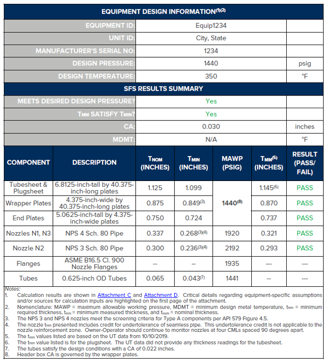
Assessment Results:
Using the methodologies outlined in the SFS project protocol document, all evaluated vessels were shown to be suitable for continued service, although for some this required repairs to individual components, addition of reinforcing elements to certain nozzles, or derating the entire vessel to a lower pressure when feasible. On occasion, inspection and data gathering efforts for the SFS project revealed damage requiring follow-up FFS assessment once the baseline SFS calculations were completed. The end result was that the owner-user was able to keep all evaluated equipment items safely in service without replacement and with minimal repairs or modifications.
SUMMARY
An SFS evaluation is the fastest and most cost-effective process for achieving OSHA compliance for equipment lacking documentation. A large-scale SFS project with a protocol document to provide guidance on roles and responsibilities, methodologies, assumptions, and documentation of results offers an efficient and effective way to evaluate a number of such equipment items on a defined schedule. Knowing when and how to justify less conservative assumptions for the evaluations can be critical in determining whether repair, alteration, or replacement can be avoided. E2G is an expert engineering service provider with the technical knowledge and practical experience to know what is required and the best way to get there. Not only can we complete the SFS evaluations in the most efficient and effective way possible, but E2G can offer a full suite of additional services and products to facilitate the full lifecycle management of fixed equipment.
For more information from the authors, please submit the form below:
REFERENCES
- API, 2023. API 510 Pressure Vessel Inspection Code: In-Service Inspection, Rating, Repair, and Alteration. The American Petroleum Institute and The American Society of Mechanical Engineers, Washington D.C./New York.