Introduction
Coke drums in delayed coker units present many reliability problems because they are subjected to unique types of damage mechanisms due to their operation. Thermal fatigue cracking is common in regions of high thermal stress due to frequent and severe thermal cycling. Bulging is also common because of this severe thermal cycling that creates hot and cold spots due to channeling effects in the coke formation that results in thermal ratcheting or progressive cyclic plastic strain accumulation.
Given the complexity of thermal loading in coke drums, simplified calculations or analysis to determine damage progression and perform fitness-for-service (FFS) for critical regions are not typically adequate. While coke drum failures are not typically high-consequence failures from a safety perspective, they do carry the financial consequence of lost production. Industry experience and guidance in documents such as API TR 934-G[1] are often utilized to make practical decisions, but in cases where damage is severe and reliability and/or safety become a significant concern, advanced analysis coupled with inspection can be a useful tool to ensure reliable operation.
Coke Drum Operation
The primary process loop in a delayed coker unit typically consists of a fractionator, a furnace, and two coke drums as shown in the schematic sketch in Figure 1. One drum is filled with heated coker feedstock that solidifies into coke in the drum. This solidified coke is then quenched and cut out of the first drum while the second drum is filled, and the process continues switching back and forth between drums. Drum filling commonly occurs over a 12 to 24-hour period, meaning the entire heating and cooling cycle for each drum repeats every 24 to 48 hours.
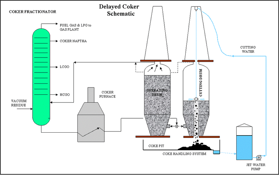
The feed temperature is typically around 900°F/482°C, with quench water temperature around 100°F/37°C. Before the feed is introduced into the cold drum, a steam preheat is performed to warm the drum to a specified “switch temperature.” This preheat step reduces the transient thermal effects on the drum from the heating side of the cycle. On the quench side after filling is complete, the cooling rates are driven primarily by the quench water temperature but can be controlled by initially introducing water at a lower flow rate. The more rapidly the heating and cooling process occurs in the drum, the more severe the transient thermal stresses. Increasing the switch temperature and reducing the quench water flow rate for a longer period of time can reduce the cyclic thermal stress range seen in critical regions of the drum, i.e., reduce the propensity to develop cracking/bulging and slow the progression of such damage; however, that comes at a cost of increasing cycle times and reducing throughput.
Advanced Analysis for Coke Drums
Skirt-to-Cone Junction Cracking
In the design phase, advanced analysis can be leveraged for design of critical drum components. This is most often seen in support skirt-to-cone junction design that is typically expected to limit the cycle life of the drum. In these cases, it is desired to establish a design fatigue cycle life and protection against ratcheting for the drum. Part 5 of ASME Section VIII, Division 2[2] (ASME VIII-2) provides methodology for assessment of protection against failure due to these cyclic loading mechanisms. Such analysis requires detailed thermal-mechanical finite element analysis (FEA) for the specific geometry and expected loading from weight, pressure, and transient thermal effects. This analysis directly assesses protection against failure from cyclic loading (ratcheting and/or fatigue) or is coupled with supplementary closed-form calculations, which are also detailed in Part 5 of ASME VIII-2 to determine the expected life of the drum.
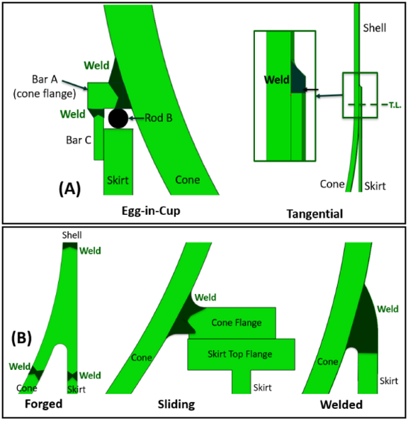
Comparative studies have been performed to assess various cone-to-skirt junction arrangements as shown in Figure 2 (see PVP2017-65807[3] and PVP2019-93529[4]), and some general trends in damage tolerance may be gleaned from such work; for example, larger cone knuckle radii and thinner/longer (more flexible) skirts would typically be expected to improve damage tolerance. However, it is important to understand that the specific geometry, even minor details of the connection, and loading for the drum cycle can have a significant impact on the results of the analysis.
In reality, many legacy skirt junction designs have not undergone rigorous analytical design, or the information, assumptions, and results from such an analysis are not maintained with the equipment. Uncertainty or irregularity in thermal cycling typical of coke drums can reduce the accuracy of such analysis if idealized assumptions are made in the design analysis. In these cases, similar analysis can be utilized in an FFS assessment using the stress analysis and fatigue methodology in Annex 2D and Part 14 of API 579-1/ASME FFS-1[5] (API 579), which is largely harmonized with the design-by-analysis methodology in Part 5 of ASME VIII-2. This is the approach that would be proactively used to predict fatigue life before any cracking is found with inspection. This sort of proactive assessment is a more common approach for design of coke drums or design/in-service assessment of other equipment in more safety-critical service such as pressure swing adsorber (PSA) vessels that process high-purity hydrogen, but it is not typically done for in-service coke drums.
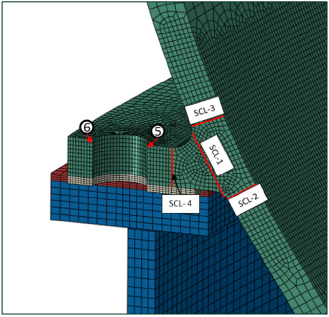
More commonly, surface inspection or volumetric ultrasonic inspection such as phased array ultrasonic testing (PAUT) is performed after some period of service, and cracking is detected and sized. These cracks typically initiate at a surface location and may propagate through the skirt or through the cone depending on the location and orientation. Generally, only cracks that can propagate through the pressure boundary (cone) are of significant concern for the remaining life of the drum. In the example shown in Figure 3 of a sliding skirt design with alignment pins, cracking along stress classification lines (SCLs) 2 and 3 as well as a crack initiating at location 5 and propagating to the right toward the inside surface of the cone are the most critical locations.
The cracking can be analyzed using API 579 Part 9 methodology coupled with FEA results in order to:
- Determine critical crack sizes, i.e., crack depth/length combinations that will not result in brittle fracture or failure of the pressure boundary, and
- Perform subcritical crack growth analysis to estimate the number of cycles until the current flaw reaches critical size.
The critical crack size analysis uses the Part 9, Level 2 failure assessment diagram (FAD) approach illustrated in Figure 4 to analyze crack-like flaws under all operating stress states throughout the cycle (determined from FEA) plus weld residual stress (if applicable) for protection against brittle fracture, plastic collapse of the remaining ligament, or elastic-plastic fracture. During the quench portion of the drum cycle, the fracture toughness may be reduced into the ductile-to-brittle transition region such that a brittle fracture could occur.
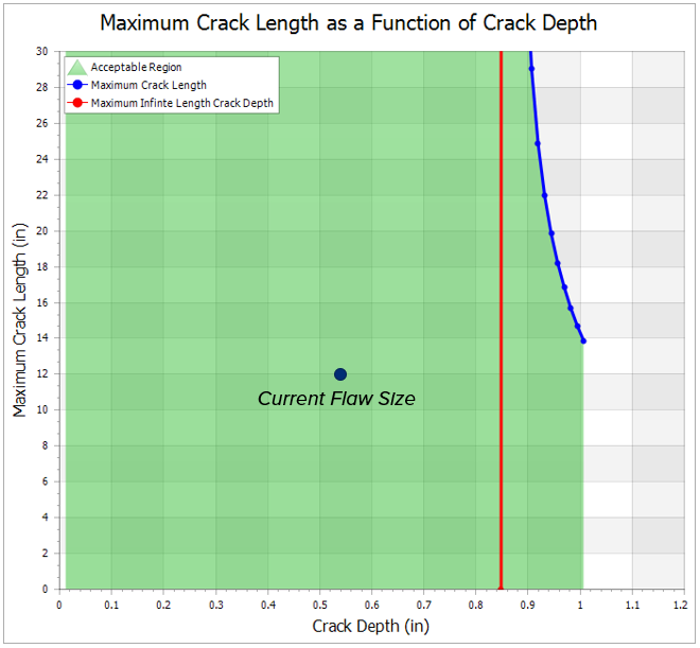
An assessment point corresponding to a particular flaw size that lies on the FAD curve represents a critical flaw size. By iterating the depth, a maximum length can be calculated and an envelope of acceptable flaw sizes can be determined. As long as the current crack(s) falls within the critical crack size envelope, there is margin on failure (see Figure 5).
To estimate the remaining life before the flaw reaches the FAD limit, subcritical crack growth analysis is performed. Crack growth analysis uses the Paris law crack growth model that determines cycle-by-cycle crack growth as a function of the stress intensity range through the drum cycle.
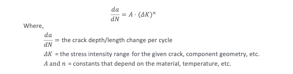
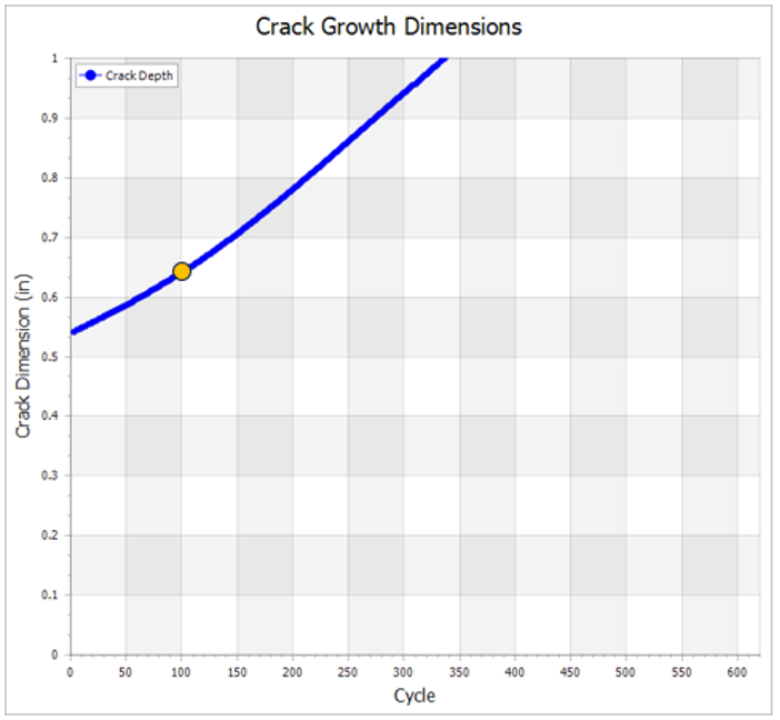
For each cycle, ΔK is recalculated based on the new crack dimensions and the process is repeated. The crack growth analysis estimates the number of predicted cycles to reach critical dimensions, which can then be coupled with PAUT re-inspection to validate the crack growth estimate and monitor growth until a planned repair or drum replacement opportunity. The example in Figure 6 shows 340 cycles to reach a critical flaw depth of 1.0 inches, and the orange point on the curve represents an expected increase in crack depth of approximately 0.1 inches over 100 cycles. With daily cycling, re-inspection after 3 months should estimate an increase in crack depth of nearly 0.1 inches. Variation in actual crack growth is possible due to irregularities in operation of coke drums and assumptions inherent in the analysis methods, which emphasizes the need to couple inspection with analysis and select frequent re-inspection intervals until crack growth rates are confirmed.
Cracking at Other Locations
Given that the skirt-to-cone junction is typically the most limiting location for fatigue cracking, it is unlikely that other regions of coke drums would be designed using advanced analysis for cyclic service. Any regions of a coke drum with large transient thermal stress gradients could be susceptible to thermal fatigue cracking. Other structural discontinuities in coke drum often include qualitative fatigue improvement methods such as flush-ground weld caps, blend-ground fillet weld toes, etc. to reduce the likelihood of fatigue damage. Although industry generally recognizes that skirt-to-cone junctions are the first places to crack on coke drums, other locations can experience cracking as well. If unmitigated, those locations can lead to failures, especially in cases where skirt-to-cone junctions have cracking repaired, effectively resetting their fatigue life.
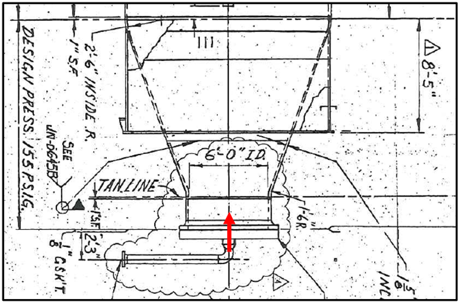
Traditionally, coke drums were filled through a central feed nozzle in the bottom bolted head, and the head would be manually removed for decoking (Figure 7). Cyclic thermal transients due to rapid flow through the feed nozzle may result in cracking, but repair or replacement is straightforward on the removable head.
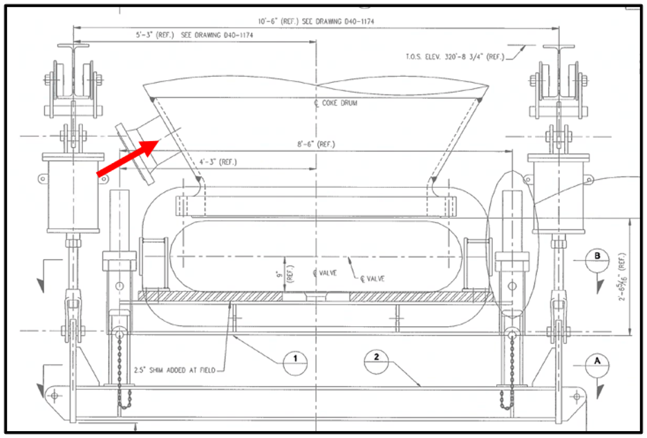
To make drum unheading/emptying safer for operators, improve cycle times, and improve reliability, modern coke drum designs since approximately 2001 utilize automated bottom unheading devices. With this arrangement, the feed nozzle typically enters through the side of the cone near the bottom (Figure 8). In some cases, this can create operational issues with irregular flow and coke formation when the feed flows directly through the nozzle and impinges on the opposite side of the cone.
To combat this effect, devices have been more recently developed that utilize internal retractable nozzles to direct flow up through the center of the drum more like traditional central feed nozzles. These devices may provide improvement both from an operational perspective by directing flow as well as a fatigue perspective by effectively acting as a thermal sleeve for the feed nozzle.
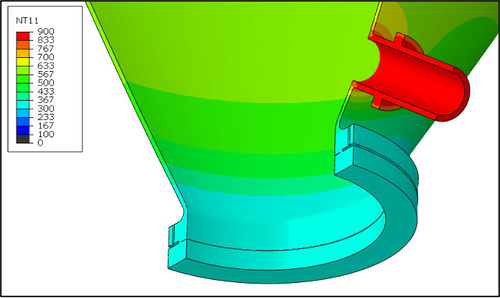
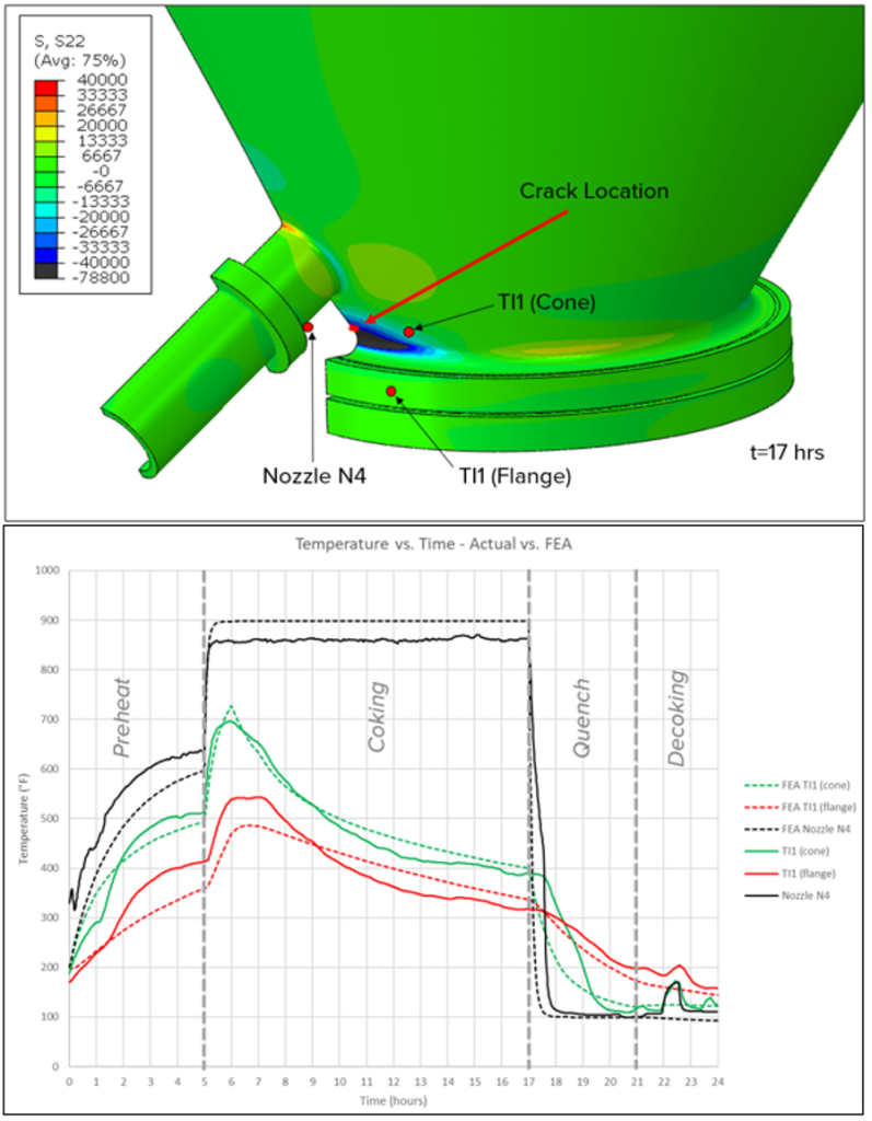
When hot and cold flow enters the feed nozzle, the nozzle itself more rapidly heats and cools relative to the cone (Figure 9).
This results in large thermal stresses at the nozzle junction (Figure 10). Since the nozzle is placed very close to the bottom of the cone, this also results in high-magnitude thermal stresses at the stiff flange-to-cone junction beneath the nozzle.
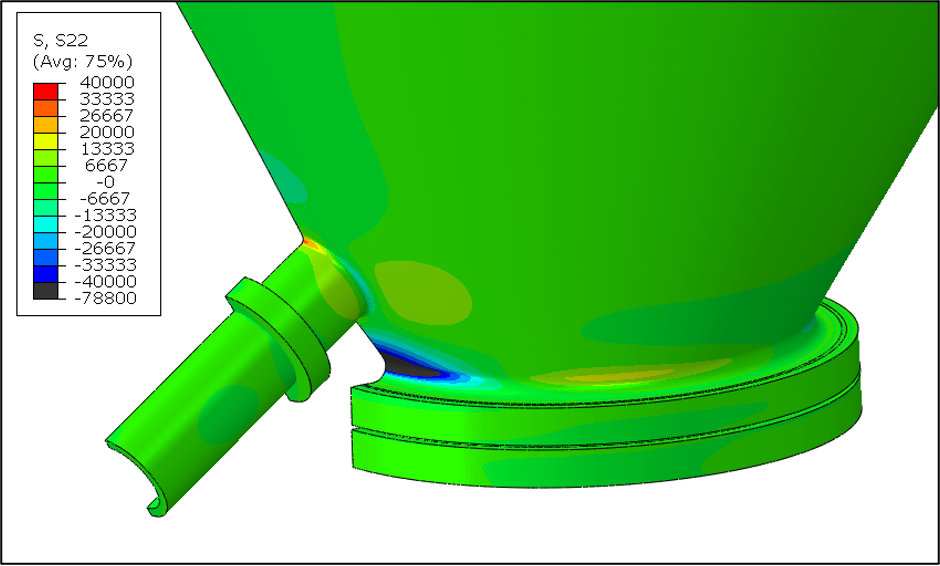
When also considering large tensile bending stresses at the OD surface of the flange hub junction due to flange bolt-up, this location can become life-limiting. The same methods for analysis of cyclic loading described above for the skirt-to-cone junction can be utilized to determine critical crack size and remaining life for feed nozzles and bottom flange junctions.
Bulging
Bulging due to hot/cold spots and thermal ratcheting is difficult to predict. Generally, minor bulging that results in out-of-roundness with diametral deviation magnitude less than 1% of the drum inside diameter (or within the construction code fabrication tolerance for out-of-roundness) would be acceptable per the API 579 Part 8, Level 1 assessment procedures.
Bulging is typically found with visual inspection and monitored for growth, most effectively with laser scanning. If progressive distortion is noted to exceed these limits, advanced analysis can be utilized to determine whether the bulging is fit for service.
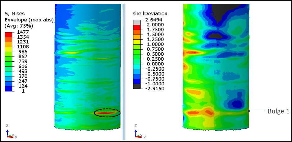
Typical advanced analysis for such bulging consists of mapping laser scan data for the affected regions of the drum onto an FEA model as shown in Figure 11 (right) and assessing if the distorted shape meets the elastic-plastic collapse and elastic-plastic (Type 3) buckling criteria under design pressure, weight, and occasional loading outlined in the Part 8, Level 3 analysis procedure and Annex 2D. This assessment addresses catastrophic failure of the bulged drum. It is difficult to predict how the bulges will grow/progress in continued service. Will they increase in depth, height, or width? Will new bulges form nearby? For this reason, the most common approach is to use a “snapshot” approach to assess the current condition of bulging, then monitor the bulges and reassess them if significant changes or increase in bulge size occur. Sensitivity analysis may be performed by varying the “severity” of bulging, i.e., scaling up the magnitude of distortion; however, it can be challenging to determine if a future state of damage falls within the assessed damage profile.
This analysis can also be used to identify the most highly stressed areas due to bulging as shown in Figure 11 (left) to help owner-users prioritize locations for inspection for cracking.
In order to fully qualify fatigue crack initiation and crack growth, local thermal data is required to accurately model temperature gradients and thermal stresses. Infrared (IR) scans may be used to identify hot spots, but the most critical required data involves installation of skin thermocouples in the bulged regions to measure surface temperature profiles through several drum cycles. This analysis can be very difficult to perform with confidence given the potential for variation from cycle to cycle and the difficulty in establishing the correct location(s) for installation of skin thermocouples. From a practical standpoint, frequent monitoring and surface inspection of high-stress regions and removal/weld repair of cracking is often the most reasonable approach.
Critical Considerations for Advanced Analysis
Visual inspection, surface inspection (such as magnetic particle testing [MT] or liquid penetrant testing [PT]), and PAUT inspection can identify and size cracking, and visual inspection supplemented with laser scan can identify and quantify bulging.
While it is possible to perform detailed thermal-mechanical FEA for structural discontinuities where cracking has been found or for bulges, more data is typically required than typical design data, operating data, and inspection findings. Typical process instrumentation does not normally provide all the data needed to perform such an analysis. The following items are critical in performing advanced analysis on coke drums:
- Local temperature data is required for thermal ratcheting, fatigue, and/or crack growth analysis.
- Wireless sensors with magnetic attachments have been successfully used to capture several drum cycles.
- Location for sensors should be based on damage; consult with the FFS analyst to determine the best placement.
- Temperature data does not always follow expectation throughout the cycle. Coke formation on the drum walls acts as an insulator and can result in cooling or a plateau of the metal temperature in certain regions far below the feed temperature; see Figure 12 where cone and flange temperatures fall off after the first hour of the coking step while the feed nozzle holds at the feed temperature.
- Critical crack size is a function of applied stress and weld residual stress (WRS).
- Modern coke drums are commonly constructed with 1.25Cr-0.5Mo base material that requires post-weld heat treatment (PWHT).
- Local PWHT after performing weld overlay or weld repair after crack removal can be challenging and if done improperly can result in cracking or distortion. As such, temper-bead weld repairs are often preferred and performed.
- Temper-bead weld repairs are allowed by Code and can greatly improve weldability, but this form of repair does not result in a reduction in WRS like PWHT. If temper-bead weld repairs are performed, the WRS will be significantly higher than the original PWHT case. While removal of cracking can extend drum life, new cracks that form at locations of weld repair without proper PWHT will be more limiting and must be reassessed.
Conclusions
Industry experience can provide practical guidance for owner-users looking to improve reliability of coke drums. For critical forms of damage that can be life-limiting, advanced analysis can be a valuable tool in life extension and replacement planning, as well as redesign efforts. E2G has experience in performing advanced analysis in these cases, and we pride ourselves not only in performing complex analysis but also balancing it with the most appropriate and practical guidance to help our clients optimize reliability and safety. Please contact the authors using the form below for any coke drum needs.
If you have any questions, please contact the authors by submitting the form below:
References
- API Technical Report 934-G, Design, Fabrication, Operational Effects, Inspection, Assessment, and Repair of Coke Drums and Peripheral Components in Delayed Coking Units, First Edition, April 2016.
- ASME Boiler and Pressure Vessel Code, Section VIII Rules for Construction of Pressure Vessels, Division 2 Alternative Rules, 2021 Edition, July 2021.
- Prueter, P.E., Bifano, M.F.P., Kummari, S.R., Hantz, B., A Comparative Study of the Thermal-Mechanical Behavior and Fatigue Life Predictions of Different Coke Drum Support Skirt Designs, PVP2017-65807, Proceedings of the ASME 2017 Pressure Vessels and Piping Division Conference, Waikoloa, HI, 2017.
- Kummari S.R., Prueter P.E., Bifano M.F.P., Further Investigation into the Damage Tolerance of Different Coke Drum Support Skirt Designs, PVP2019-93529, Proceedings of the ASME 2019 Pressure Vessels and Piping Division Conference, July 14-19, 2019, San Antonio, TX, USA.
- API 579-1/ASME FFS-1, Fitness-For-Service, December 2021.