Introduction
The need for recognized and generally accepted good engineering practices (RAGAGEP) related to post-construction equipment repairs and maintenance has drastically increased over the last 30 years as owner/operator engineering standards and best practices scarcely provide detailed guidance and information on post-construction equipment maintenance and repair. This industry-wide need ultimately led to the formation of the ASME PCC (Post-Construction Committee) and subsequent creation of the ASME PCC-1 and PCC-2 documents, which are broadly used across industry today. These standards have proven to be a valuable resource for the industry, and many owner/operators have decided to adopt these documents as corporate practices and best practices.
But significant gaps remain in the guidance available in the PCC documents, and by their very nature as industry standards, they are required to be somewhat general and generic. The Equity Engineering Practices (EEPs) build on the foundation of ASME PCC-2 and provide additional and detailed insight on welded repairs, mechanical repairs, and non-metallic repairs for in-service pressure vessels and piping as a part of the EEP’s comprehensive collections of engineering standards.
Equity Engineering Practices (EEPs) 7-3-X Series
The 7-3-X series within the EEPs consists of several engineering practices that provide supplementary guidance and repair methods over the base ASME PCC-2 standard and are listed below:
- EP 7-3-3: Welded Repairs of Pressure Equipment and Piping
- EP 7-3-4: Mechanical Repairs of Pressure Equipment and Piping
- EP 7-3-5: Non-Metallic and Bonded Repairs of Pressure Equipment and Piping
The structure of EP 7-3-3 is a paragraph-by-paragraph commentary on PCC-2 Articles 201 through 214 in the form of revising, adding, or substituting wording based on extensive review and collaboration by E2G’s subject matter experts in equipment repair.
The focus of this article will be using EP 7-3-3 for welded repairs of pressure equipment and piping and highlighting a few specific cases where the EP provides clarity, guidance, and added utility by providing significant additional information above and beyond PCC-2.
Providing Specific Guidance Lacking in PCC-2
Article 204 – Welded Leak Box Repair
Article 204 is widely used in industry as a guideline for the manufacture and installation of welded leak enclosures. Different from a mechanically bolted leak enclosure, a welded leak box is a custom leak repair device that is generally fabricated from various piping, fitting, and plate components and is welded to the damaged component to temporarily mitigate a leak or defect. The design of a welded leak box enclosure to encapsulate a leaking or damaged component is generally viewed by maintenance engineers as a relatively simple exercise. In reality, the design considerations for a welded leak box extend further than simply designing component thickness for internal pressure. Some questions to ask yourself when designing a welded leak box are:
- Am I using the “correct” code of construction?
- Should I consider effects of thermal expansion?
- Should I consider effects of low-temperature operation?
- How can I safely install this leak box with the damaged component in service?
E²G’s Article 204 overlay provides insight to the above questions as well as specific guidance lacking in the PCC-2 version, such as:
- A specified minimum corrosion allowance (para. 3.7)
- Specified joint efficiencies (para. 3.8.a)
- Inspection requirements for both the damaged component (para. 3.11) and the enclosure (para. 5.3)
- Gap tolerances for leak box installation and recommended methods to deal with excessive gap (para. 4.2)
- Minimum acceptable thickness values for the component to be repaired at the weld location, including suggestions to deal with low-thickness components (para. 4.4)
Article 201 – Butt-Welded Insert Plates
Butt-welded insert plates are a common repair method used to restore corroded wall thickness, remove local non-volumetric damage, and even facilitate maintenance execution scope where large openings are needed for equipment ingress and egress into the vessel confined space. Performing a butt-welded insert plate repair involves replacing a shell cutout of predetermined size with new material attached via full-penetration butt welds. Although advancements in automated weld restoration have made large-scale shell weld restoration and overlay projects more efficient and cost-effective, butt-welded insert plates are still widely used in industry as a cost-effective method of repair.
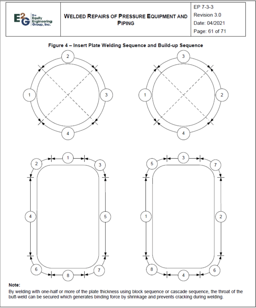
A common issue associated with installing butt-welded insert plates, especially on equipment items with larger D/t (D = diameter, t = thickness) ratios, is managing local distortion during the welding process. This becomes increasingly more important when the insert plate is to be installed near a structural discontinuity such as a nozzle, shell seam, or head-to-shell junction as stress in these areas due to local distortion and weld residual stress becomes increasingly more difficult to quantify near these discontinuities. A common misconception is that the use of very stiff, local restraint around the opening where an insert plate is to be installed will reduce shell distortion and, therefore, reduce local residual stresses in the repair area. While it may minimize during the welding process, the risk of weld cracking after removal of the restraint is much higher as the repair area is released to its post-repair position. Rather, a controlled welding process and detailed plan should be utilized to minimize shell distortions. Supplemental to the guidance on this topic provided in PCC-2, Figure 4 from EP 7-3-3 shown below provides some basic guidance for insert plate welding sequences for basic rectangular and circular shapes to assist with distortion control during the welding process.
Filling Gaps in PCC-2 – Article 205 – Weld Ring Gaskets (Welded Lip Seals)
Weld ring gaskets, also commonly referred to as a welded lip seal, are used in critical flange pair applications both by design from the manufacturer and as an alternative to replace failed conventional gaskets where leakage is unacceptable. PCC-2 Article 205 addresses weld ring gaskets but leaves much to be desired in terms of details and guidance. While welded lip seal gaskets are not intended to be used as a repair or solution for problematic bolted joints utilizing conventional gaskets without first understanding the root cause of leakage, their utilization can effectively produce leak-free operation with proper design and installation practices. A welded lip seal consists of two metallic rings that are welded to their respective flange face via an attachment fillet weld prior to joint assembly and subsequently welded together on the periphery of the rings. Typical flat lip seal and hollow lip seal weld ring configurations are shown below:
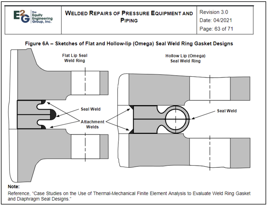
Flat lip seal weld rings are predominantly used in applications when the two mating flanges are geometrically identical and there is little to no differential thermal expansion between the flanges. For applications where differential thermal expansion is expected to occur (e.g., a heat exchanger channel-to-shell girth flange), a hollow lip “Omega” seal weld ring offers much better compliance with radial, differential, thermal expansion. E2G has extensive experience with industry research, development, and root-cause failure analysis of welded lip seal gaskets. E2G was the primary contributor and author to the PVP2018-84910 research paper titled “Case Studies On The Use of Thermal-Mechanical Finite Element Analysis to Evaluate Weld Ring Gasket and Diaphragm Seal Designs.” The paper highlights an extensive computational study of a failed seal weld on a flat lip weld ring gasket in a high-pressure heat exchanger service. Several iterations of the analysis were performed to understand sensitivity of the lip seal ring fillet weld stresses to design variables such as:
- Geometry of the weld rings (flat lip vs. hollow lip designs)
- Assumed friction coefficient on contact surfaces
- Amount of applied bolt preload
- Inclusion of flexible graphite insert on weld ring gaskets
- Modifying diaphragm gasket material
- Size of the diaphragm gasket seal weld
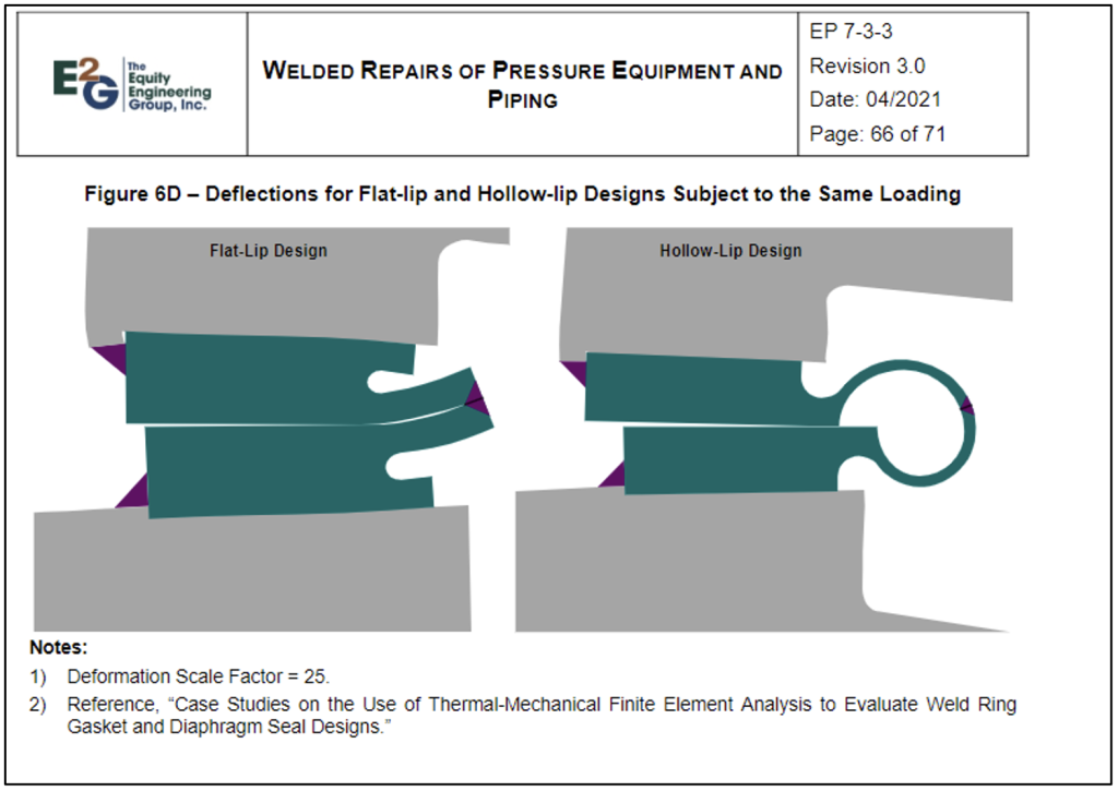
The results of this case study that are highlighted in PVP2018-84910 form the basis for the additional expert guidance provided EP 7-3-3 that is only mentioned in ASME PCC-2 in a relatively basic capacity. As an example, Figure 6D below from EP 7-3-3 presents a visual representation of the improved compliance to radial expansion in a hollow lip design over a flat lip design that is otherwise not expanded upon in the base PCC-2 article.
Even in applications where differential thermal expansion is not expected to occur, differences in flange geometries or flange stiffnesses may result in detrimental flange rotation and subsequently damage the welded lip seal during flange assembly and bolt-up. Therefore, for problematic joints or cases with thermal gradients, it is recommended that a detailed finite element analysis (FEA) evaluation is performed to quantify stresses during bolt-up and in normal operation.
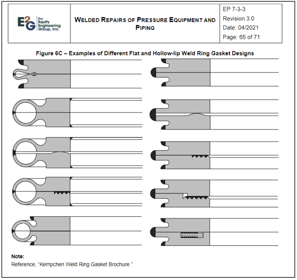
There are several options available to improve the seal ability and reliability of a welded ring gasket that are not covered within PCC-2. The geometry of the welded ring profiles can be designed to facilitate larger amounts of flange rotation by providing a small gap between the welded rings. Additionally, auxiliary gaskets may be used in conjunction with the welded ring gasket. An auxiliary gasket is typically set in (or machined in) to one of the ring faces and provides an additional defense mechanism against leakage. Figure 6C below from EP 7-3-3 shows additional examples of various ring geometries and auxiliary gasket designs.
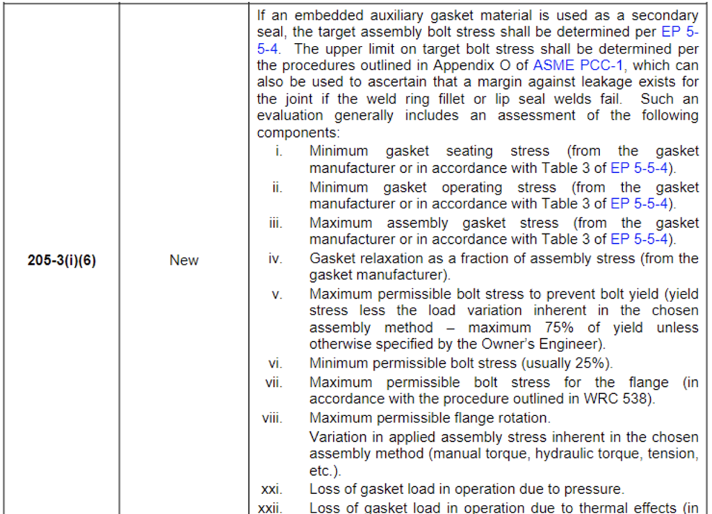
When utilizing an integral auxiliary gasket to provide improved joint sealing, a different approach for determining assembly bolt loads must be considered. When solely relying on the welded lip seal for protection against joint leakage, the calculated bolt load is only required to account for pressure thrust loading and any external axial forces or moments per PCC-2. An excerpt from EP 7-3-3 is shown below to describe the calculation of assembly bolt stress when utilizing auxiliary gaskets in tandem with welded lip seal gaskets.
E2G has extensive experience performing detailed evaluations of welded lip seal gaskets. Utilizing EP 7-3-3, practices users will find valuable information on welded lip seal gaskets that draws on this extensive experience and results in a more reliable and safer flanged joint.
A Comprehensive Look at Welded Repairs – The Rest of the Article 200 Series
The EPs also include detailed guidance and specific recommendations on the full range of other welded repair methods in PCC-2, from Article 202 external weld buildup to repair internal thinning to Article 214 field heat treatment of vessels, which contains extensive guidance on performing local post-weld heat treatment of vessels, based largely on a PVP paper written by E²G and published as PVP2016-63581.
Conclusion
PCC-2 has become an industry standard document to assist owner-users in managing pressure equipment repairs, but it is imperfect and not specifically tailored to your site’s needs. E²G’s PCC-2 overlays contained in EPs 7-3-3, 7-3-4, and 7-3-5 help fill the gaps and provide the extra context, details, and guidance to provide more comprehensive solutions for post-construction equipment repairs.
If you have any questions for the authors, please submit the form below:
References
- Prueter, P.E., Davis, R.C., Rodery, C., McJones, S., Brodzinski, R., Havekost, J., Feddeler, D.E., “Case Studies on the Use of Thermal-Mechanical Finite Element Analysis to Evaluate Weld Ring Gasket and Diaphragm Seal Designs,” PVP2018-84910, Proceedings of the 2018 ASME Pressure Vessels and Piping Conference, Prague, Czech Republic, July 15-20, 2018.
- Prueter, P.E., Macejko, B.R., “Establishing Recommended Guidance for Local Post Weld Heat Treatment Configurations Based on Thermal-Mechanical Finite Element Analysis,” PVP2016-63581, Proceedings of the 2016 ASME Pressure Vessels and Piping Conference, Vancouver, BC, Canada, July 17-21, 2016.