Abstract
When designing or revalidating pressure relieving systems for heat exchangers, it is crucial to consider the possibility of internal tube failure, specifically the occurrence of a sudden tube rupture that can cause overpressuring of the low-pressure side of the exchanger above its maximum allowable working pressure. This article presents E2G’s method to assess the credibility of the tube rupture overpressure scenario.
TRCA
API STD 521, titled “Pressure-relieving and Depressuring Systems,” provides requirements for analyzing the credibility of instantaneous tube rupture and designing overpressure protection for the low-pressure side of the exchanger. Users must either assume the full-bore overpressure scenario is credible and implement adequately sized relief protection, or deem the tube rupture scenario not credible after conducting a detailed analysis that demonstrates its remote likelihood.
E2G’s tube rupture credibility assessment (TRCA) methodology involves a series of analysis steps to review the heat exchanger design and operation, aiming to conclude that tube rupture is unlikely. The TRCA procedure aligns with API STD 521 and serves as a basis for determining whether the pressure relief system (PRS) on the low-pressure side needs to account for the full-bore tube rupture scenario. E2G has a high success rate in eliminating the need for expensive modifications to the relief device installation after conducting over 130 TRCAs.
E2G’s TRCA approach comprises four key components that address the requirements outlined in API STD 521 to determine the credibility of the tube rupture scenario.
Tube Vibration Analysis and Erosion Check
In heat exchangers, various vibration mechanisms can lead to detrimental effects on tube arrays. Fluid-elastic whirling/instability causes large-amplitude random vibrations when flow velocity exceeds a critical value, resulting in baffle fretting and mid-span tube collisions. Vortex shedding occurs when vortices form on the backside of tubes, causing resonant vibrations if shedding frequency is close to the tube’s natural frequency. Tube collision parameters assess the likelihood of mid-span collisions based on flow and baffle restraint forces, with fatigue and tube material endurance influencing failure. Acoustic vibration, whose frequency is dependent on shell diameter and fluid velocity, can damage tubes when the shell resonates due to vortex shedding or turbulent buffeting. Preventing excessive vibrations and tube damage requires careful consideration, and evaluation is performed using specialized software to compare expected vibrations to acceptable limits based on TEMA standards and HTRI methods.
Metallurgical and Corrosion Assessment
This analysis focuses on verifying the suitability of the tube material for the service and assessing potential damage mechanisms such as cracking, brittle fracture, creep, and aggressive corrosion. If there is a significant susceptibility to stress corrosion cracking, brittle fracture, or creep, the possibility of tube rupture becomes more credible due to the sudden nature of these mechanisms. However, corrosion alone is not decisive as it can be effectively managed through targeted inspection programs and leak detection systems. The assessment evaluates credible damage mechanisms based on the operating conditions and stream composition of both the shellside and tubeside. The primary focus is on identifying damage mechanisms that could lead to instantaneous tube rupture, including environmental stress corrosion cracking, brittle fracture, and creep. Additionally, corrosion damage mechanisms such as pitting and localized corrosion are considered to address any past or potential aggressive corrosion issues. While active corrosion mechanisms do not automatically increase the risk of instantaneous tube rupture, a well-designed inspection program and leak detection systems provide adequate mitigation to eliminate this risk.
Tube-to-Tubesheet Joint Design Assessment
The review of the tube-to-tubesheet joint design aims to assess its susceptibility to fatigue and tube pullout. While API STD 521 primarily focuses on fatigue, tube pullout, which can result in a similar high-pressure flow as tube rupture, is also considered. Axial load calculations are performed to ensure the joint’s capability to withstand thermal and pressure differentials. Additionally, the susceptibility to axial and circumferential buckling is verified using methodologies outlined in ASME Section VIII Division 1.
Tubes pulling out of the tubesheet can cause an event resembling tube cracking or rupture, leading to two paths of flow from the high-pressure to low-pressure side of the exchanger. ASME provides criteria for evaluating the tube-to-tubesheet joint’s ability to withstand axial forces caused by thermal and pressure differentials between the shell and tubeside components. In most cases with a significant pressure differential, strength welding is employed for the tube-to-tubesheet joints. Tube pullout is primarily a concern for fixed-fixed tubesheet exchanger designs. U-tube designs have inherent flexibility, resulting in lower axial stress on the tubes. Rolled and expanded-type joints are generally sufficient to address pullout concerns for U-tube bundles, although these should still be checked as part of the TRCA. In cases where the exchanger experiences frequent thermal and/or pressure cycles, a fatigue assessment of the tube-to-tubesheet joint should also be conducted.
Review of Bundle Inspection Program
API STD 521 requires an appropriate bundle inspection program to monitor damage mechanisms that could lead to tube rupture. The existing program is reviewed to ensure alignment of inspection frequency and methods with suspected damage mechanisms and tube material. If no suitable program is in place, one must be established. Inspection histories are assessed to identify thinning or cracking issues that could potentially lead to tube rupture.
Selection of tube bundle inspection techniques depends on the tube material and expected defect types. Generally, techniques recommended for damage mechanisms of concern for tube rupture detection include those capable of identifying flaws or defects caused by environmental cracking, localized corrosion, and contact-related cracking at tube-baffle interfaces. Additionally, localized corrosion may occur in stagnant areas at the backside of the tubesheet near the tubeside inlet. Non-destructive testing (NDT) techniques available for tube bundle inspection include conventional eddy current testing (ECT), full-saturation ECT, remote field eddy current testing (RFET), magnetic flux leakage, ultrasonic internal rotary inspection system (IRIS), and laser optics. Each technique has its advantages and limitations. For example, conventional ECT is sensitive to pits and cracks but limited to non-ferromagnetic materials, while IRIS accurately measures wall thickness but may miss small defects like pinholes and cracks. Optical techniques are limited to internal defects. As NDT techniques continually evolve, it is crucial to seek guidance from knowledgeable NDT contractors to ensure proper technique selection for heat exchanger tube inspection.
It should be noted that the quality of results from ECT and other testing techniques heavily relies on the operator’s skill. Operators should be adequately trained and demonstrate their ability to locate defects on sample tubes with known defects.
Furthermore, it is important to inspect the tube-to-tubesheet joint and tubesheet ligaments using penetrant testing (PT) inspection, particularly when the exchanger is exposed to mechanical and/or thermal cycles that could result in fatigue cracks. Fixed-fixed tubesheet exchangers are more susceptible to this type of damage compared to exchangers with floating heads or U-bends.
Case Study
Recently, an Owner-User in the refining industry requested a TRCA be performed for a compressor discharge cooler. The cooler is protected by a single pressure relief valve (PRV) located off the exchanger at some distance via direct line from the exchanger. The TRCA was requested to verify that the full-bore tube rupture was not a credible scenario for this exchanger and that the PRS did not need to be redesigned to account for this scenario.
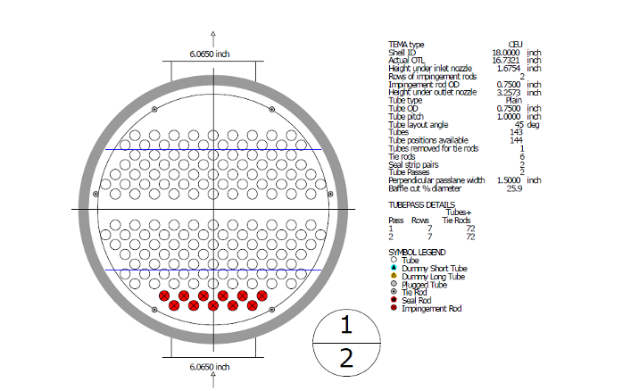
The exchanger operates with chilled water on the shellside and compressor discharge on the tubeside. The chilled water enters the shellside at 45˚F and 60 psig with a flowrate of 237,000 lb/hr. The compressor discharge enters the tubeside at 100˚F and 1650 psig and exits the exchanger at 55˚F. The compressor discharge stream on the tubeside is composed primarily of hydrogen with small amounts of methane, ethane, and propane. The tubes are 0.75-inch outer diameter with a 0.109-inch wall thickness made of 2205 duplex stainless steel. The tube-to-tubesheet joint is strength-welded and roller-expanded into two grooves. A representation of the tube layout details is depicted in Figure 1.
Tube Vibration Analysis and Erosion Check
The vibration analysis was performed in key areas of the exchanger: shellside inlet, shellside outlet, center, bundle entrance, and bundle exit. The analysis focused on the areas with the longest unsupported span of tubes. Additionally, erosion checks were performed at the shellside inlet, shellside outlet, center regions, and the shell entrance and exit areas. The results of the vibration analysis and erosion check are presented in Table 1 and Table 2. The analysis indicates that the bundle is not at risk of vibration damage.

Metallurgical and Corrosion Analysis
The U-tubes in the cooler are seamless, eliminating concerns regarding tube rupture from weld seam defects or selective weld seam corrosion caused by shellside chilled water. The SA-789 2205 duplex stainless steel material used for the U-tubes is not susceptible to brittle fracture under the provided operating conditions. Stress relieving was performed after bending, eliminating concern for cracking. No metallurgical changes or embrittlement mechanisms are expected at the operating temperature.
Possible damage mechanisms for the tubeside and shellside are outlined in Table 3 and Table 4, respectively. Several process-side corrosion mechanisms were identified and determined to be not credible due to the use of a resistant alloy tube material. Chloride stress corrosion cracking (CSCC) was considered to have a low probability of occurring but was ruled out since the U-bends had been adequately stress relieved.
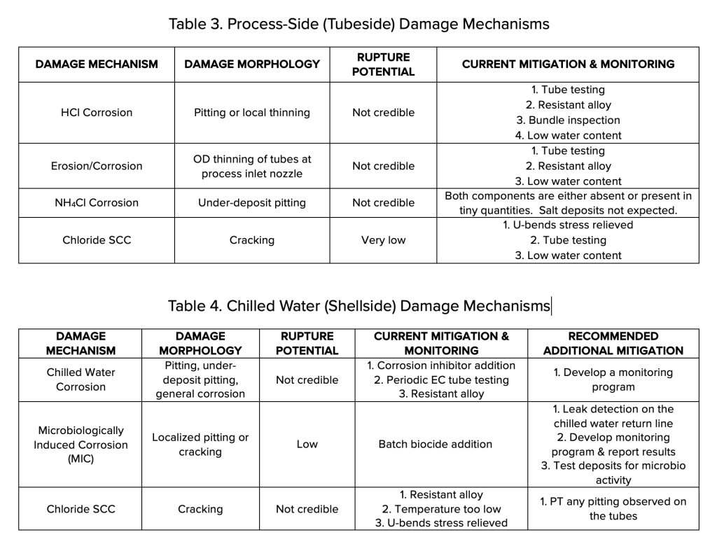
Although the chilled water on the shellside undergoes batch corrosion inhibition and biocide addition, there was no existing monitoring program for the water. As a contingency for passing the TRCA, it was recommended to improve the chilled water monitoring program. The potential damage mechanisms can be effectively managed by conducting periodic (every 10 years or less) ECT of the tubes.
Tube-to-Tubesheet Joint Design
The tube-to-tubesheet joint’s maximum load capacity per the ASME Code due to pressure thrust was calculated to be 4,241 lbs, while the actual axial load on the tubes from internal pressure is only 442 lbs. Additionally, the thermal stress contributes 399 lbs, resulting in a combined loading of 842 lbs from pressure and temperature, which is only 10% of the maximum Code allowable combined load of 8,482 lbs. Therefore, the likelihood of tube pullout is negligible.
To assess the bundle’s susceptibility to tube buckling, the critical axial load and required tube thickness were determined. The critical axial load for buckling is calculated as 16,420 lbs, while the actual axial compressive load from thermal effects is 399 lbs, representing only 2.43% of the critical axial load. The required wall thickness for the tubeside design pressure is 0.0306 inches, which is 28.1% of the tube’s furnished thickness. As a result, tube buckling and collapse are not a concern.
Review of Bundle Inspection Program
The original carbon steel bundle in the cooler had a history of corrosion and plugging, leading to multiple retubing instances. More recently, a new bundle made of duplex stainless steel was installed, and no leaks have been reported since. To comply with API STD 521’s requirement for an appropriate tube inspection program, the Owner-User should develop a program targeting damage mechanisms that could result in a full-bore tube rupture. For 2205 duplex stainless steel tubes, ECT is suitable for assessing corrosion metal loss and cracking, while ultrasonic testing (UT) using IRIS can effectively identify general or local corrosion thinning. Furthermore, PT inspections of the tubesheet face should be conducted to check for strength weld leaks and tubesheet ligament cracking.
Case Study Conclusion
After a comprehensive review of the compressor discharge cooler’s design and operating conditions, it was determined that the heat exchanger satisfied the criteria outlined in API STD 521. Consequently, the tube rupture scenario was deemed non-credible. However, for this conclusion to hold, the Owner-User must implement an appropriate inspection program, adhere to the recommended additional mitigation measures, and ensure that any future mechanical or process changes relating to the exchanger undergo a thorough review through the management of change process, without affecting the outcome of this analysis.
As a result, there is no need to redesign the PRS for the low-pressure side of the compressor discharge cooler to accommodate full-bore tube rupture. This is particularly advantageous as the low-pressure side of the exchanger is filled with liquid. In the event that the tube rupture scenario was considered credible, a transient analysis would be necessary to determine the required reaction time and capacity of the PRS. This analysis would likely indicate the need to replace the PRV with a larger, faster-acting rupture disk.
Final Thoughts
API STD 521 is the guidebook when it comes to analyzing PRSs. The standard identifies a list of overpressure scenarios that the process designer needs to consider when assessing overpressure protection requirements for new or existing equipment. The tube rupture scenario is considered to be somewhat of a remote scenario, and usually mitigating an existing relief system for deficiencies associated with the tube rupture scenario will result in significant capital expenditures. API STD 521 allows the tube rupture scenario to be deemed as non-credible if a rigorous assessment, such as the TRCA, is conducted. E2G strongly recommends that a TRCA be conducted before any capital expenditures are incurred to mitigate deficiencies associated with the tube rupture scenario.
If you have any questions for the author, please submit the form below: