Midstream pipelines are considered critical infrastructure in the energy sector because they transport oil, gas, and other fluids over long distances. Due to the complexity and scale, pipelines are susceptible to leaks that can result in severe environmental, economic, and safety consequences. Effective leak detection (LD) program management is necessary for mitigating these risks, but it is not enough to have an LD system, it must be designed and installed properly. The LD must be regularly maintained so it is reliable and available when needed, with the systems tuned to specific operating situations and conditions.
This article provides an overview of the key technologies and practices used in pipeline monitoring and leak detection. In addition, the article discusses the importance of LD in ensuring the safe and efficient operation of pipeline infrastructure.
Table 1 provides an overview and categorization of LD systems as per API RP 1175.
| External Monitoring | Internal Monitoring | ||||
| Physical Inspection | Sensor-Based Monitoring | Manual Observations | Computational Pipeline Monitoring (CPM) | ||
| Non-Continuous Monitoring | Aerial Surveillance | Ground-Penetrating Radar | Volume or Line Balance Calculations | ||
| Ground-Based Line Surveillance | Sniffer Tubes | Hydraulic Calculations | |||
| Hydrotesting | Tracer Chemicals | Pattern Recognition | |||
| Satellite | Intelligent Pigs | Shut-In Testing/Stand-Up Testing | |||
| One-Call System/ Public Awareness | Soil Sampling | ||||
| Continuous Monitoring | Sensing Cables | Controller SCADA Monitoring | |||
| Cameras | Real-Time Line Balance | ||||
| Chemical Analyzers | Pressure Monitoring | ||||
| Acoustic Sensors | Pattern Recognition | ||||
| CP Monitoring | Digital Signal Analysis | ||||
| Statistical Analysis | |||||
External Leak Detection Systems
External systems focus on monitoring the environment outside the pipeline for signs of leaks.
Non-Continuous Monitoring
These methods are applied periodically rather than continuously, often as part of routine inspections or when a potential issue is suspected.
Physical Inspection
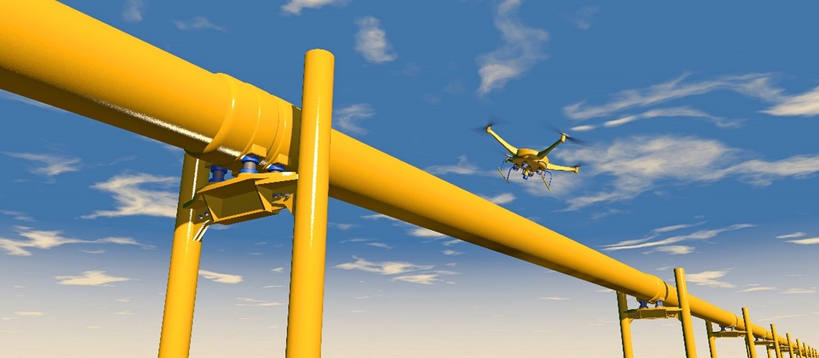
Aerial Surveillance is increasingly being employed by the petrochemical industry, utilizing drones for early pipeline leak detection, especially in remote areas. With the use of advanced technologies such as thermal, visual, and infrared cameras, these drones provide operators with methods that are more accurate and efficient than traditional approaches for detecting gas leaks in pipelines. Drones offer a faster alternative for pipeline inspections as they are quick to deploy and easy to operate; they can also be programmed to follow specific routes for detailed inspection of targeted areas. Utilizing drones for routine inspections improves worker safety by eliminating the need for personnel to enter hazardous zones.
Ground-Based Line Surveillance is a technique that requires operators to walk or drive along the pipeline route to visually inspect for signs of leaks or damage. However, this method is impractical due to the challenging terrain through which pipelines run. Visual inspection is labor-intensive and can pose safety risks to the operator.
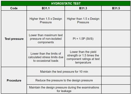
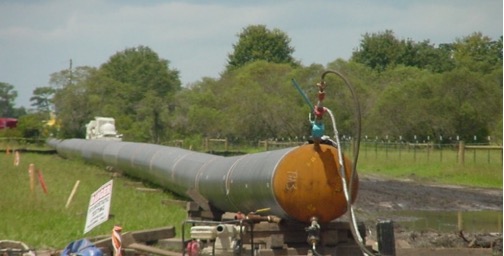
Hydrotesting is a process where the pipeline is filled with water. Pressure is slowly applied to the water until the appropriate test pressure is reached. The test pressure should not be less than 1.5 times design pressure, and the duration is kept as 10 minutes.
Pressure-sensing devices such as pressure gauges monitor the pressure to assess the pipeline’s integrity and strength as well as to detect any leaks.
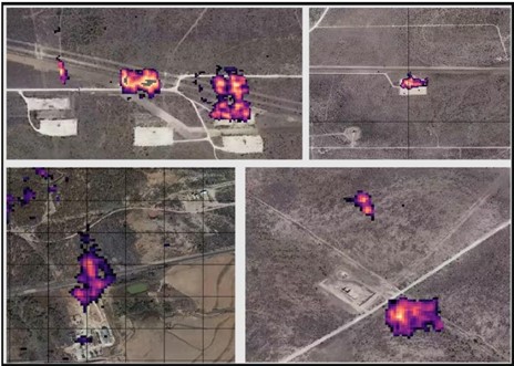
Satellites equipped with sensors can monitor large areas for environmental changes that might indicate a leak, such as vegetation stress, temperature anomalies, or soil shifts.
Orbital Sidekick (OSK) developed the Global Hyperspectral Observation Satellites (GHOSt 1 and GHOSt 2) as part of its GHOSt constellation. The first two satellites in the constellation were launched on April 15, 2023. The GHOSt satellites are equipped with hyperspectral sensors that can detect wavelengths up to 2,500 nanometers, which is farther into the infrared than traditional satellites. They can capture 472 bands of light across the electromagnetic spectrum, which is 100 times more spectral information than can be captured by traditional satellites. OSK’s hyperspectral imagery technology can be used to detect leaks.
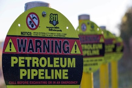
One-Call Systems are used to notify pipeline operators before any digging occurs near pipelines to prevent accidental damage. The nationwide number for the one-call system in the United States is 811.
The purpose of the public awareness program is to inform the public about essential steps to prevent or reduce pipeline emergencies by promoting safe excavation practices. The public is encouraged to report any suspicious activity or potential pipeline damage. This program also educates the public on the correct actions to take in the event of a pipeline release or emergency.
Sensor-Based Monitoring
Ground-Penetrating Radar (GPR) is an electromagnetic geophysical technique that sends radio wave pulses at select center frequencies into the ground to study the subsurface leakage. If a wave pulse encounters a material interface of sufficiently different electromagnetic properties, some of the energy is reflected back while the remainder continues to propagate. This technology sends radar waves into the ground to detect buried objects or changes in soil density. It can be used to locate leaks or assess the condition of buried pipelines [7].
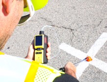
Sniffer Tubes are leak detection devices designed to identify the presence of hydrocarbon gas that escapes from holes or cracks in pipes after a tracer gas has been introduced to the system. The tubes collect and analyze air samples along the pipeline to detect for the presence of hydrocarbons. Sniffer tubes are effective for detecting small gas leaks but are typically used only in specific locations, such as near joints and valves. By accurately detecting hydrocarbons, technicians can pinpoint the exact location of the leak and thus allow for efficient repair and maintenance of the affected pipes. Using hydrocarbon gas leak detectors ensures the safety and integrity of underground pipe networks and prevents potentially hazardous situations caused by undetected leaks.
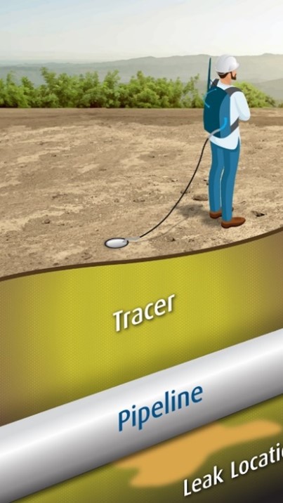
Tracer Chemicals are injected into the pipeline, after which the chemical trace instrument is moved along the surface of the pipeline. If a leak is present, the instrument detects the tracer chemical. This technology is flexible and quickly detects leaks because the instrument can be either walked over the ground above the pipeline or mounted on a vehicle. It is important to note that tracer chemical leak detection operates without any need to insert probes [10].
Intelligent Pigs is a process that starts with the device traveling through the pipeline; as the smart pig moves through the pipeline, it detects anomalies such as corrosion and wear, cracks, pipeline geometry, pipeline wall thickness, and/or leaks. Detailed data is collected and transmitted to the surface.

Soil Sampling is an important technique for detecting leaks in buried, underground pipeline. By analyzing soil samples taken from around the pipeline, operators can identify contamination or changes in soil properties caused by leaked substances. Various soil sampling methods are used depending on the pipeline’s location, the type of substance transported, and environmental conditions.
Continuous Monitoring
Continuous monitoring systems provide real-time data, allowing for quicker detection and response to leaks.
Sensor-Based Monitoring
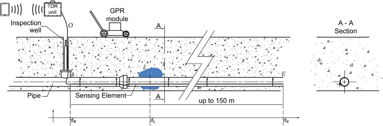
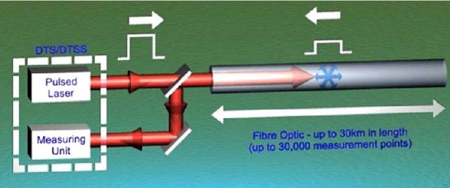
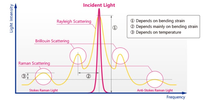
Fiber Optic Sensing Cables can be installed on a buried or unburied pipeline and laid alongside the pipeline. The fiber acts as a continuous sensor, detecting changes in the environment around the pipeline. A combination of Rayleigh, Brillouin, and Raman backscatter phenomena is used to detect leaks.
Rayleigh backscatter is primarily used for Distributed Acoustic Sensing (DAS). By monitoring changes in the backscattered light, the system can detect acoustic vibrations along the pipeline, which may indicate leak, unauthorized excavation, or other disturbances.
Brillouin backscatter is used in Distributed Temperature Sensing (DTS) and Distributed Strain Sensing (DSS). It helps monitor changes in temperature and strain along the pipeline that can be indicative of leaks, ground movement, or structural stress.
Raman backscatter is primarily used in Distributed Temperature Sensing (DTS). By analyzing the intensity of the Anti-Stokes component of the backscattered light, the system can accurately measure temperature changes along the pipeline.
Cameras, fixed or mobile, can be used for pipeline monitoring. Mid-wave infrared cameras are utilized to detect and visualize hydrocarbon gas emissions. Cameras can detect leaks, unauthorized activities, or environmental changes, and they are often used in high-risk areas.
Chemical Analyzers continuously monitor the air or soil around the pipeline for the presence of a wide range of substances including hydrocarbons, volatile organic compounds (VOCs), and other chemical signatures associated with the fluids transported through pipelines.
Chemical analyzers can be installed at fixed locations along the pipeline or used as portable devices for on-site inspections. Fixed analyzers provide continuous monitoring, while portable analyzers allow for targeted inspection. These are placed in areas where leaks are most likely to occur near joints, valves, or known weak points. The sampled substance is analyzed using techniques such as gas chromatography, infrared spectroscopy, or mass spectrometry to identify the presence of specific chemicals that can indicate a leak. Chemical analyzers are highly sensitive tools and can detect even small concentrations of leaked substances.
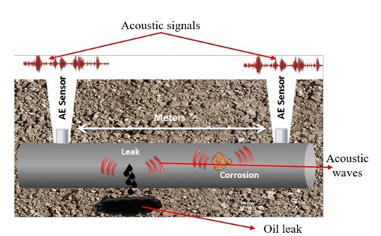
Acoustic Sensors used for leak detection operate on the principle that escaping fluid generates an acoustic signal as it passes through a crack in the pipe. When a leak occurs, acoustic sensors installed along the pipeline detect and track this signal as it travels. The signal’s magnitude is stronger near the leak, helping to pinpoint its location. The system processor then analyzes the detected acoustic signal using signal processing techniques [15].
Cathodic Protection (CP) Monitoring is primarily used to prevent pipeline corrosion, but it can also be an indirect method for detecting leaks in pipelines. CP systems protect metal pipes from corrosion by applying a controlled electric current, creating a protective layer that inhibits corrosion. Changes in the CP system’s performance can sometimes indicate a leak.
CP systems maintain a protective electrical current across the pipeline, thereby preventing corrosion by making the pipe’s surface more cathodic (negative) than its surroundings. A sudden drop in the CP potential or current levels can indicate a breach in the pipeline’s protective layer, which could be due to corrosion or physical damage such as a leak. If the pipeline is compromised and fluid escapes, it disrupts the CP current or alters the electrochemical environment, thus leading to noticeable changes in the CP readings.
Note that CP monitoring is not a direct leak detection method and may not identify all leaks, particularly ones that are small or slow.
Internal Leak Detection Systems
Internal systems focus on monitoring the pipeline’s internal conditions, such as pressure, flow, and temperature, to detect leaks.
Manual Observations (Non-Continuous Monitoring)
Volume or Line Balance Calculations – The volume of fluid that enters the pipeline over any time interval minus the volume of fluid that exits the pipeline over the same time interval (T0 to T1) must be equal to the change in fluid volume inside the pipeline over the same time interval (pipeline inventory).

Under a no-leak condition, the leakage volume will be zero. Note that this method is simple to implement [14].
Hydraulic Calculations are also referred to as the hydrostatic method when utilized in leak detection. This method examines the pipeline in a static hydraulic state. To verify the integrity of the pipes, they are sealed and pressurized with water, oil, or other fluids. Pre-installed pressure sensors then monitor the pressure within the pipeline to detect any reductions that could indicate the presence of a leak [16].
Pattern Recognition in pipeline leak detection can be via manual observation or involve advanced algorithms and machine-learning techniques to analyze data and/or detect anomalies. In the case of manual pattern recognition, the operators manually analyze historical data to identify trends that might signal a development of leak. This method requires expertise and can be time-consuming.
Shut-In Testing / Stand-Up Testing detects leaks in pipelines by isolating a section of the pipeline and monitoring pressure stability over time. This technique to assess pipeline integrity is often employed in oil and gas pipelines and other fluid transport systems.
A specific section of the pipeline is isolated by closing valves at both ends, thereby sealing the segment from normal operations. The isolated section is then pressurized to a predetermined level. This pressure can be applied using the existing fluid in the pipeline or by adding additional fluid to reach the desired pressure. Once pressurized, the section is left in a “shut-in” state and the pressure is monitored over a set period. During this time, sensors or pressure gauges continuously record the pressure within the isolated segment. A stable pressure reading throughout the test duration indicates that the isolated pipeline section is free of leaks. However, if there is a noticeable drop in pressure, fluid may be escaping from the pipeline, indicating the presence of a leak. If a pressure drop is detected, further analysis is conducted to determine the leak’s location, size, and potential causes. This may involve additional testing or the use of other leak detection methods.
Manual Observations (Continuous Monitoring)
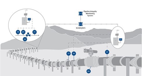
Controller SCADA Monitoring – Most Supervisory Control and Data Acquisition (SCADA) systems are automated and accompanied by manual observation. Operators monitor real-time data feed and alerts, making decisions based on their analysis. Continuous monitoring allows for immediate intervention when anomalies are detected.
Manual observations are exposed to human error, such as misinterpretation of data or the overlooking of small anomalies. Manual observations can also be slower. Appropriate training and experience are required for manual monitoring of SCADA.
Computational Pipeline Monitoring (CPM)
Computational Pipeline Monitoring (CPM) system creates a digital model of the pipeline at normal operating conditions. Mass flow rates, pressures, and other parameters such as temperature sensors and valve positions are used by CPM to continuously compare real-time data against the digital model.
Continuous Monitoring
These systems continuously monitor various parameters within the pipeline, allowing for real-time detection and response.
Conservation of Mass principle is used in real-time pipeline leak detection systems by tracking the mass balance of the fluid inside the pipeline system to identify discrepancies. The amount of product entering and leaving the pipeline system is measured and compared with the volume flowing through various sections.

ΔM represents the change in the mass of the fluid in the pipeline due to leaks or internal processes.
This method considers not just the inflow and outflow but also accounts for fluid storage, compressibility, temperature changes, and other dynamic factors along the entire length of the pipeline system.

Real-Time Line Balance principle is used in real-time leak detection systems by comparing inflow vs. outflow across a segment of the pipeline. Flow meters are placed along the pipeline at the entry (inlet) and exit (outlet) point. This method is less complex, simpler to install, and used across only a small section compared to conservation of mass method.
Pressure Monitoring involves the continuous monitoring of pressure throughout the pipeline. Pressure transmitters are installed at critical points, including the inlet, outlet, and intermediate locations. A normal operating pressure profile is established based on historical data and operating conditions. Any gradual or sudden drop in pressure can indicate the presence of a leak.
Pattern Recognition involves the use of advanced algorithms and machine learning techniques to analyze data from various sensors. This method identifies patterns that indicate normal operation and detects anomalies that could signal a leak. This powerful tool in modern leak detection systems offers high sensitivity and the ability to detect subtle or complex leak indicators that might be missed by traditional methods.
Pipelines are equipped with various sensors such as pressure sensors, flow meters, temperature sensors, and acoustic detectors. These sensors continuously monitor the pipeline’s operational parameters, generate substantial amounts of data, and capture information about the pipeline’s normal operational patterns and any anomalies that occur. Machine learning models are trained on historical data to recognize patterns associated with normal pipeline operations and those indicative of leaks. The trained models continuously analyze incoming data in real time and compare it against learned patterns. The system identifies deviations from the normal operating condition that may suggest a leak.
Digital Signal Analysis identifies anomalies via analysis of signals from various sensors such as acoustic, pressure, temperature, and flow. Advanced algorithms including machine learning are used to detect anomalies by continuously monitoring signal patterns and detecting deviations from normal behavior that may indicate a leak.
Statistical Analysis continuously collects data, such as acoustic, pressure, temperature, and flow, from sensors to compare results against the baseline data. This sensor data comparison identifies the section of pipeline where the anomaly originated. In addition, changes in pressure or flow at specific locations can be statistically analyzed to pinpoint the leak’s location.
Conclusion
Midstream pipelines play a vital role in the energy sector by transporting oil, gas, and other fluids over long distances. The distance combined with complexity makes them vulnerable to leaks; therefore, implementing an effective LD program is essential to minimizing these risks. The mere installation of an LD system is not sufficient; it must be carefully designed, continuously maintained, and tuned for various operational conditions. A robust approach that integrates both external and internal monitoring systems in accordance with 49CFR Part 195.134 and recommended practices such as API RP 1175 and API RP 1130 is key to ensuring reliable, real-time detection and management of leaks. Further LD system specification is provided in Equity Engineering’s EP 20-9-1 – Control Systems for Pipeline.
Please submit the form below with any questions for the author:
References
[1] API RP 1175
[2] https://energyhq.com/2017/01/drone-technology-makes-pipeline-inspections-a-breeze/
[4] https://allaboutpipelines.com/Article/PrecommissioningHydrotest
[5] https://www.eoportal.org/satellite-missions/ghost#missionstatus
[6] https://www.genesisenergy.com/operations/onshore-facilities-and-transportation/public-awareness
[7] https://www.epa.gov/environmental-geophysics/waterborne-ground-penetrating-radar
[8] https://ietresearch.onlinelibrary.wiley.com/doi/10.1049/iet-smt.2016.0310
[9] https://www.forensicsdetectors.com/blogs/articles/hydrogen-detector-underground-pipes
[11] https://epcmholdings.com/magnetic-flux-leakage-inline-inspection/
[12] A. Ukil, W. Libo, and G. Ai, "Leak detection in natural gas distribution pipeline using distributed temperature sensing," IECON 2016 - 42nd Annual Conference of the IEEE Industrial Electronics Society, Florence, Italy, 2016, pp. 417-422, doi: 10.1109/IECON.2016.7793562
[13] https://www.anritsu.com/en-us/sensing-devices/guide/fibersensing2
[14] https://www.emerson.com/documents/automation/best-practices-in-leak-theft-detection-en-5396684.pdf
[15] Adedeji, Kazeem B., Hamam, Yskandar, Abe, B.T., & Abu-Mahfouz, Adnan. (2017). Towards Achieving a Reliable Leakage Detection and Localization Algorithm for Application in Water Piping Networks: An Overview. IEEE Access. 5. 20272 - 20285. 10.1109/ACCESS.2017.2752802
[16] Wang, Xiao-Jian, Simpson, Angus, Lambert, Martin, & Vítkovský, John. (2001). Leak detection in pipeline systems using hydraulic methods: a review
[17] https://www.napipelines.com/the-evolution-of-pipeline-leak-detection/#google_vignette
[18] https://www.emerson.com/en-ca/industries/automation/oil-gas/pipeline-integrity-leak-detection