Introduction
Pressure swing adsorbers (PSAs) are critical to gas separation and purification technology, but these vessels present a unique set of maintenance and reliability challenges due to their inherently severe cyclic operation. A detailed lifecycle management plan anchored in engineering and fitness-for-service (FFS) can provide significant benefits to PSA vessel reliability while maximizing the equipment life. A remaining life and inspection optimization study is a critical supplement to a prescriptive (API 510) or risk-based inspection (API 580/API 581) program in quantifying inspection needs for equipment in severe cyclic fatigue service. From a process safety standpoint, identifying the critical locations to inspect and establishing required inspection timing are essential parts of an integrity management program for PSAs. Many pressure equipment jurisdictions and governing bodies now require owner/users to explicitly manage equipment in fatigue service with inspection programs and to understand and establish the associated remaining life. Not only can a preemptive fatigue study guide inspection frequency to effectively balance equipment risk with focused inspection expenditures, but it can also support the extension of life for in-service equipment that may have exceeded the original equipment design fatigue predictions. This article will describe how a fatigue and fracture study can guide inspection plans throughout the life of a typical PSA vessel population. Details will also be provided on considerations to process environment, weld peaking, and original design features.
Background
PSA technology is commonly used for efficient separation and purification of gases, typically hydrogen, through a series of pressure “swings.” The adsorption phase of the cycle occurs at higher pressures, at which the target impurities are preferentially trapped by the adsorbent material releasing a high purity gas product for recovery. The adsorbent material is then regenerated by depressurizing the PSA, which allows for the trapped impurities to be vented. This pressurization and depressurization cycle is repeated quite frequently, in some cases up to 30 times per hour. This pressurization and depressurization cycle produces an alternating stress state that is conducive to the accumulation of fatigue damage. Without a thorough remaining life and inspection optimization study, this fatigue damage may cumulatively progress and manifest itself in the form of crack initiation and subsequently crack propagation that may result in equipment failure if not managed properly. It is common in industry for existing PSA vessels to have been fabricated in accordance with ASME Section VIII Division 1 (ASME VIII-1), which contains no explicit requirements for design of equipment in fatigue service. Additionally, it is common for vessels to be in operation with no remaining design fatigue life. This does not necessarily mean that the PSA is at the end of its useful life, and it is likely that a considerable amount of additional remaining life can be justified by a comprehensive inspection strategy focused on monitoring for crack-like flaws at the locations identified as most susceptible to fatigue damage by a detailed fatigue assessment . This comprehensive inspection strategy is typically guided by the results of a design fatigue life assessment and a crack growth assessment.
Design Fatigue Life Assessment
To further understand how much fatigue damage a PSA has accumulated, a fatigue life assessment should be performed. For PSAs designed and constructed in accordance with ASME Section VIII Division 2 (ASME VIII-2), the User Design Specification (UDS) may include a fatigue design life which can be used to guide remaining life and likely areas of damage initiation. As mentioned previously, however, it is common that this assessment was not performed as part of the original design for vessels constructed in accordance with ASME VIII-1. To fill this gap, fatigue life calculations are performed using the methodologies provided in Part 14 of API 579-1/ASME FFS-1 (API 579), which are analogous to the procedures provided in ASME VIII-2. To determine the membrane and bending stresses for use in the assessment of fatigue life at critical locations, a finite element model (FEM) is created, and an elastic stress analysis is performed. Stress linearization is then performed on the FEM at all critical pressure-boundary locations, allowing for the determination of membrane and bending stresses through the thickness of the pressure boundary along a stress classification line (SCL). Additional considerations for peaking (discussed in further detail below) are also incorporated in this fatigue evaluation.
A typical FEM model of a PSA vessel with critical SCL locations is shown in the figure below:
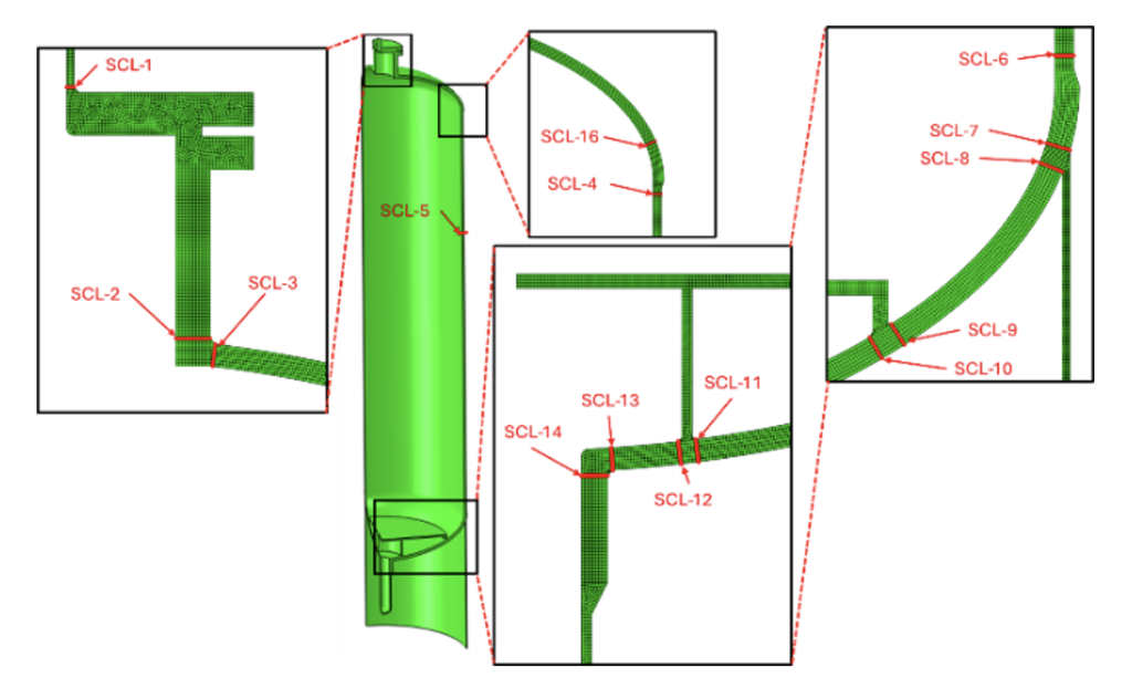
Note that mechanical fatigue is predisposed to originate at welds due to the discontinuities and defects inherent to welded construction; cracking most typically manifests as surface flaws parallel to weld toes.
A design life assessment can be performed using ASME smooth bar methods for non-welded components, and the equivalent structural stress methods for welded components. Various international codes can also be used for alternative fatigue assessment methods. The intent of the fatigue design life calculations is to define the vessel’s current damage state and support future inspection focus. Based on the results of the fatigue calculations, location-specific inspection guidance and recommendations can be obtained, and are generally grouped into three categories:
- Significant Remaining Fatigue Life: Future vessel remaining life is not expected to be governed by these locations.
- Inspection Recommendation: Detailed cracking inspection beyond an initial baseline cracking inspection is not typically required.
- Nearing End of Design Fatigue Life: Fatigue damage could progress into detectable cracking at these locations.
- Inspection Recommendation: Detailed cracking inspections should be included in future inspection plans.
- End of Design Fatigue Life: These are the highest-risk locations for fatigue cracking failure.
- Inspection Recommendation: Detailed cracking inspections should be included in future inspection plans, and on-stream monitoring of critical locations should be considered.
For locations that are identified as nearing or at the end of their design fatigue life, further fracture-based crack growth analysis should be completed and paired with a thorough inspection plan to facilitate continued operation of the PSA and further define required inspection intervals. A more detailed discussion on crack growth analysis is provided later in this article.
Considerations for Peaking
Fatigue life can be drastically decreased and crack growth rates drastically increased on vessel longitudinal weld seams when the effects of weld peaking (misalignment) are considered. Weld seam peaking generally occurs during fabrication and is defined as a local deviation from a true circular cross-section at the weld seam. The figure below shows an example of outward peaking:
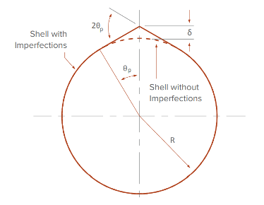
Peaking induces a higher bending stress local to the weld seam, with high stress on the OD of the vessel in the case of inward peaking, and high stress on the ID in the case of outward peaking. The negative effect of peaking on fatigue design life is generally understood across the industry. In fact, most PSA vessel specifications indicate that any amount of peaking is unacceptable upon completion of fabrication. However, it has been E2G’s experience that measurable amounts of peaking can be identified even when indicated as unacceptable on the fabrication documentation. This is likely due to difficulties obtaining consistent and reliable results when using traditional “centered” or “rocked” template measuring technique. In fact, a study by Cayard and Geisenhoff [1] estimated that the magnitude of measured peaking values was underestimated by as much as 50% when utilizing traditional template techniques. To illustrate the effects of introducing 50% measurement error into fatigue life design calculations, consider the example below for two different peaking measurements at the same theoretical location on a PSA longitudinal weld seam. An increase of 50% on the measured peaking value resulted in a 45% increase in fatigue damage after the same cycle life. While this example does not capture all possible scenarios, it is a helpful illustration of the importance of accurate peaking measurements.

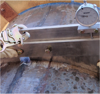
From the same Cayard and Geisenhoff [1] study, a hinged style template with a dial gauge, as shown below, was able to produce more accurate and repeatable peaking measurements. Alternatively, modern laser scan methods have proven to be an accurate method of taking longitudinal seam peaking measurements.

Crack Growth Assessment Background
So how do you manage continued operation of your PSA vessels once a design life assessment indicates there are welded locations with no remaining fatigue life? A crack growth assessment is generally recommended for those locations that are near or have exceeded the design fatigue life and offers perspective on the time required for an initially detectable flaw to propagate to failure. The lower bound for flaw size detectability when using modern inspection techniques such as phased array ultrasonic testing (PAUT) and time-of-flight diffraction (TOFD) may be on the order of 0.0625 inches deep. This flaw depth is therefore used as the postulated initial flaw, just below the limits of detection from the date of the most recent inspection. The time associated with flaw growth until failure is then estimated; failure in this case is defined as the flaw depth exceeding 80% of the wall thickness, or the flaw growing beyond the critical flaw definition.
The simplest model for crack growth is the Paris Equation, as shown below:
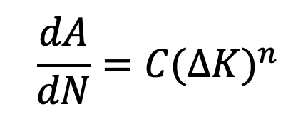
Where,
Hydrogen Aggressive vs. Non-Aggressive Operating Environments
API 579 lists multiple Paris Law coefficients for different materials and service conditions. As of writing this article, API 579 does not provide explicit guidance for crack growth in carbon steels operating in pure hydrogen environments (>99.9% hydrogen purity). Typically, PSAs will not solely be operating in pure hydrogen environments; near the end of the adsorption cycle, however, hydrogen purity levels may increase to above 99.9%, further increasing the need to understand the sensitivity to crack growth in hydrogen operating environments. Several thorough literature reviews have been performed to determine the primary factors affecting the fatigue lives of carbon steel PSA vessels in hydrogen operating environments. As a result of testing by Somerday and Barney [2], a modified power-law distribution can be used to establish a da/dN vs. ΔK relationship for use in FFS evaluations of carbon steel PSAs operating in hydrogen aggressive environments. A comparison between the hydrogen environment test data from Somerday and Barney [2] and the API 579 non-aggressive environment relation is shown in the figure below.
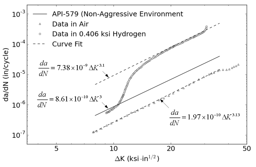
Similar to the considerable effect peaking has on fatigue life and crack growth rates, hydrogen purity can also have a significant impact. Since there is no time or hydrogen purity dependent test data available, E2G recommends a crack growth sensitivity study be performed utilizing the crack growth rates (da/dN) for the curve fit line in the figure above. An example of the significance of crack growth rate sensitivity to a hydrogen operating environment is shown in the figure below for a theoretical longitudinal weld seam on a PSA.
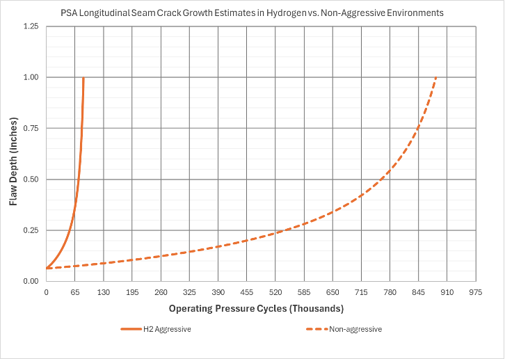
Considering a pure hydrogen operating environment for the same location decreases the operating pressure cycles to the critical flaw depth by approximately 90%. Considering a pure hydrogen operating environment is a method of placing a conservative upper bound on crack growth rates with currently available test data. Due to the effects of inhibitor gases, actual crack growth rates in real world applications will likely be considerably less than the aggressive rate shown here. Therefore, utilizing the hydrogen aggressive crack growth coefficients in a crack growth assessment may yield overly conservative or unrealistic results that present challenges when setting inspection intervals and PSA remaining life estimates. However, performing a sensitivity study by assuming a pure hydrogen operating environment provides an additional lens to focus on the critical areas of the PSA for future inspection and operational planning.
Crack Growth Results and Inspection Planning to Guide Continued Operation
Results from a crack growth assessment are not intended to be an exact determination of time necessary for an initially detectable flaw to reach critical dimensions. Rather, these results provide perspective on the necessary inspection type and interval to ensure that an undetectable flaw is not likely to grow to failure before the next available inspection opportunity. A typical approach to establish re-inspection intervals for locations that have consumed ‘design’ fatigue life is based on a half-life approach. These re-inspection intervals should be implemented after a detailed initial flaw inspection has been completed on all PSA welds. A detailed initial flaw inspection is critical to identify flaws that may be related to fabrication defects and not necessarily driven by the effects of fatigue. A good example of this in PSA vessels is the skirt-to-head attachment weld, which is a notoriously difficult weld position to make without any defects. Results from a fatigue and crack growth assessment may indicate that fatigue-related crack initiation and subsequent crack growth is unlikely. However, cracking at this location is prevalent and typically related to fabrication defects. By ignoring an initial baseline flaw inspection and solely relying on a fatigue and crack growth assessment to guide future inspection efforts, it is possible that cracking at some locations such as the skirt-to-head weld may go undetected and result in an unanticipated failure.
Conclusion
Lifecycle management of PSA vessels can be a daunting task, especially when the PSA was not originally designed with fatigue in mind and a post-construction fatigue assessment indicates that the vessel has consumed all of its design fatigue life. However, E2G has helped numerous owner-operators safely and effectively manage PSA vessels well beyond their design fatigue life by using the analysis methods and inspection recommendations discussed in this article. This is a prime example of how preemptive engineering and FFS strategies can provide significant benefits to equipment reliability while also maximizing capital investments.
References
- Cayard, M., and Geisenhoff, M., 2017. “Detriment of Peaking on Longitudinal Welds in CCR Heater Transfer Lines and Methods for Inspection.” In 7th Biennial API Inspection Summit. American Petroleum Institute. Galveston, Texas
- B. P. Somerday and M. Barney, “Measurement of Fatigue Crack Growth Relationships In Hydrogen Gas for Pressure Swing Adsorber Vessel Steel,” J. Press. Vessel Technol., vol. 137, no. 2, pp. 1–7, 2015.