Fitness-for-service (FFS) assessments are key to evaluating the integrity of aging assets. FFS assessments come in three levels (1, 2, and 3), with increasing complexity and decreasing conservatism. Levels 1 and 2 are often employed by asset owners and operators due to their simplicity. However, these methods can be overly conservative, leading to unnecessary and costly repair and maintenance activities. Level 3 assessments require advanced numerical methods, like Finite Element Analysis (FEA), and are the gold standard for FFS evaluations.
FEA has several advantages but comes at the price of heightened complexity. FEA can model the geometry, damage, operating conditions, and material properties accurately and provide results with a very small margin of error. However, there are several factors that can make FEA prohibitive:
- High barrier to entry: FEA has historically required highly qualified experts with deep knowledge of FEA theory and experience using complex commercial software.
- Time-consuming model setup: Over 70% of an FEA analyst’s time is often spent on model preparation, especially meshing.
- Resource-intensive: FEA demands the availability of high-performance computing resources.
- Costly software: Commercial FEA software is expensive, with licensing fees often covering several features irrelevant to the task at hand.
- Inefficient for inverse problems: Real-world measurements often cannot be directly used in FEA models, necessitating multiple iterative cycles – increasing time and cost.
The Cloud Solution
Equity Software has developed a cloud-native, automated FEA solution – the FEA Suite. Leveraging our expertise and experience in advanced nonlinear FEA and the scalability of the cloud, the FEA Suite is built to deliver an efficient, comprehensive, and cost-effective solution for modern asset management. These powerful tools are the result of direct client feedback and more than eight years of rigorous research. They handle the complexities of FEA with ease and address several issues associated with traditional FEA:
- Accessible expertise: The FEA Suite simplifies Level 3 assessments to the point that they are as easy to use as Level 2 tools.
- Improved efficiency: Built-in automation for model building, mesh generation, and post-processing allows engineers to focus on engineering judgment and decision-making.
- Cloud-native architecture: No need for on-premise high-performance computers – everything runs in the cloud with integrated 3D visualization.
- Focused applications: Tailored for asset integrity tasks, the FEA Suite ensures users have the tools they need to solve their most pressing problems in a reproducible manner.
- Massive scalability: The cloud platform enables fast, parallelized execution of iterative analyses and parametric studies, condensing weeks of work to less than an hour.
By automating the model building, mesh generation, and post-processing steps, as well as integrating parallel execution on the cloud, the FEA Suite enables users to conduct advanced stress and damage assessments with improved efficiency, reproducibility, and accessibility. Table 1 shows a side-by-side comparison of traditional FEA methods with Equity Software’s FEA Suite, highlighting how key pain points in the conventional way FEA is performed are overcome.
Table 1: Traditional FEA Approach Vs. Cloud-Based Approach to FEA Challenges
| Challenge Area | Traditional FEA | Cloud-Based Approach |
| Ease of Access | Requires experts with deep FEA theory and software knowledge | As simple to use as Level 2 tools – accessible to a broader range of users |
| Modeling Efficiency | Analysts spend 70%+ time on model setup and meshing | Automated model building, meshing, and post-processing streamline the entire workflow |
| Computational Resources | Requires local HPC infrastructure or costly cluster maintenance | Fully cloud-native – no local computing resources needed |
| Cost Structure | Expensive licenses with many unused features | Pay-per-application model tailored to asset integrity needs |
| Handling Inverse Problems | Iterative cycles with field data add time and cost | Scalable cloud architecture enables fast parallel iterations and parametric sweeps |
| Turnaround Time | Weeks for complex assessments | Hours – through automation and cloud scalability |
| Customization | General-purpose tools not optimized for asset management | Purpose-built tools designed specifically for stress and damage assessments |
This article explores several of the key advantages of cloud computing and automation and how these technologies will revolutionize the field of asset evaluation and management. We begin by understanding the cloud computing architecture of the FEA Suite that enables efficient and comprehensive calculations, followed by a brief introduction of the three existing tools in the FEA Suite. Subsequently, we delve into specific use cases highlighting the strengths and capabilities of these tools in real-world assessment scenarios to demonstrate how automation and distributed computing enable engineers to overcome limitations of the traditional approach to Level 3 assessments. The article concludes with a forward-looking discussion on the future direction of this approach, including its potential limitations, areas for further development, and implications for broader industry adoption.
Scalability and Efficiency: The Cloud Architecture
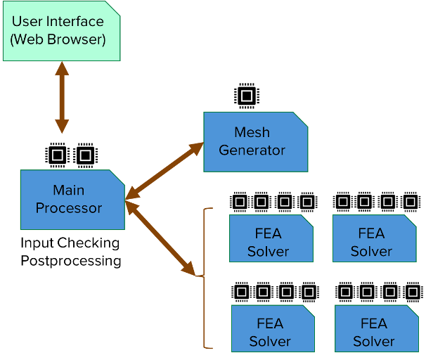
One of the main advantages of the FEA Suite is its scalable and dynamic cloud architecture, which significantly enhances efficiency and performance while reducing both cost and computation time. The key to this scalability is the division of Level 3 assessments into modular sub-tasks. Each computational task, such as model building, meshing, and FEA, is orchestrated with a network of individual virtual machines, with resources allocated based on the task-specific requirements.
As shown in Figure 1, when a user initiates a calculation via the web interface, a main processor is launched which validates the user inputs. A separate auxiliary virtual machine is then created to handle model building and mesh generation and is automatically decommissioned once the finite element mesh is generated. Following this, one or more FEA Solver machines is deployed to perform the large numerical simulations. These FEA Solver machines are provisioned with higher memory and processing power to support computational demands. When parametric sweeps or iterative analyses are required, multiple solver instances run in parallel. Once the FEA is completed, the FEA Solver machines are decommissioned, and the results are returned to the main processor for post-processing.
All auxiliary machines communicate with the main processor, enabling real-time status tracking of each FEA task by the user. The entire system is dynamically orchestrated, ensuring lean, efficient, and task-specific use of computational resources.
Where We Are: The Current Toolset
Equity Software currently includes three advanced FFS tools: Dent FEA, Tank Settlement FEA, and Local Thinning FEA as part of the FEA Suite. These tools feature automated model generation that transform parameters used for Level 2 assessments into high-fidelity FEA models. They incorporate advanced data mapping capabilities to integrate real-world field data directly into the simulations. Leveraging distributed cloud computing, the tools offer scalable and efficient performance for complex assessments. Post-processing is conducted in accordance with API 579 and ASME BPVC Section VIII, Division 2, ensuring compliance with the latest versions of the codes. The results from all three tools have been verified against Abaqus to ensure accuracy and reliability. A web-based 3D visualizer is also provided with the tools to view the key result fields like stress and strain.
Dent FEA: Precision Dent Modeling
The Dent FEA tool performs a Level 3 assessment of dents and evaluates the local damage and fatigue life. While it is mainly targeted towards pipeline integrity assessments, the tool is also applicable to cylindrical pressure vessels. In addition to plain dents, the tool supports the modeling of dents with gouges, a frequently co-occurring and critical form of damage.
MORE FROM INDUSTRY INSIGHTS
Are Dents Really a Problem?
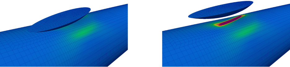
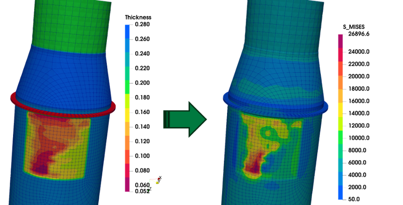
Using user-defined parametric inputs (e.g., pipeline geometry, material specifications, indenter type, and dimensions) and the pressure history, the tool automatically constructs a detailed 3D finite element model using 20-node brick elements to capture stress concentrations and plastic deformation with high fidelity. When applicable, the tool leverages model symmetries with appropriate boundary conditions to optimize computational efficiency without compromising accuracy, significantly reducing model size and solution time. Figure 2 shows the results of the indentation and subsequent pressurization of a cylinder, simulated using the Dent FEA tool.
The Dent FEA tool offers two modes of use:
- FEA Model Generation – Users can export the FEA model in a format compatible with Abaqus, enabling advanced users to run custom simulations or integrate the model into a larger analysis pipeline.
- Fully Automated FFS Assessment – Alternatively, the tool can perform the entire FFS assessment, delivering results in line with API 579 and industry best practices. When used to perform a full evaluation of the severity and long-term impact of a dent or gouge, the tool provides a suite of key engineering parameters as follow:
- Local damage factors, including strain-limit damage (SLD) and ductile failure damage (DFDI)
- Peak equivalent stress and strain values
- Radius of curvature, rebound, and reround
- Fatigue life estimation under cyclic pressure loading
- Stress and strain contours to identify local plasticity and stress triaxiality
Tank Settlement FEA: Versatile Solution for Bottom Settlement
The Tank Settlement FEA tool is a specialized application designed to evaluate the effects of ground settlement in aboveground storage tanks. Using an axisymmetric finite element model, the tool can simulate both edge-settlement and arbitrary radial settlement profiles, offering flexibility to evaluate the more critical scenario.
The tool supports a wide range of geometrical configurations, including:
- Floating or fixed roofs
- Multiple bottom plates with lap-welded and butt-welded connections
- Stiffener rings
- Cone-up, cone-down, and flat bottoms
- Global and local corrosion on shell courses and bottom plates
In terms of analysis capability, the tool performs both global and local assessments, each of which may be characterized as follows:
Global Assessments:
- Plastic collapse assessment using elastic analysis, including stress linearization and allowable stress evaluation at critical welds
- Plastic collapse assessment using elastic-plastic analysis, providing a more accurate estimation of design margin
- Ratcheting assessment to evaluate incremental deformation under cyclic loading
Local Assessments:
- Critical flaw screening at the annular plate-to-bottom shell weld, performed automatically in accordance with Part 9 of API 579
- Plastic strain evaluation based on ASME BPVC Section VIII, Division 2
The combination of geometric flexibility and multiple analysis modes makes this tool highly versatile for engineers performing comprehensive FFS assessments of aboveground storage tanks affected by ground settlement.
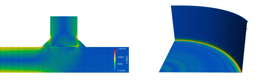
The visualizer for the Tank Settlement FEA tool can be used to view the results in the axisymmetric (planar) view or rotated (3D) view (Figure 3). The planar view is better suited to understanding the stress profiles and differential settlement, while the 3D view offers a visualization resembling the actual geometry.
Local Thinning FEA: Comprehensive Thinning Assessment
Local thinning due to corrosion and erosion is the most common form of damage in pipelines and pressure vessels. The Local Thinning FEA webtool allows users to automatically perform a comprehensive Level 3 FFS assessment on pipelines and pressure vessels with local and general thinning. It supports the modeling of thinning on cylinders, heads (spherical, ellipsoidal, torispherical), conical transitions, and 90-degree bends (elbows). The tool can perform both internal pressure (burst) and external pressure (buckling) assessments and supports supplemental loads (weight and thermal).
One of the strengths of this tool is its ability to deliver Level 3 accuracy using essentially the same input as that required in a Level 2 assessment. Moreover, unlike traditional Level 2 methods, it can reliably assess thinning near geometric discontinuities or in the presence of multiple interacting thin regions – areas where Level 2 approaches are not applicable.
The tool transforms simple parametric inputs based on field measurements into comprehensive Level 3 insights. User inputs, including geometry selection, dimensions, material properties, operating conditions, and thinning profiles, are automatically transformed into a 3D finite element model using 20-node brick elements. Thickness profiles based on field measurements are automatically mapped onto the mesh using advanced interpolation techniques, with localized mesh refinement in thinned areas to capture stress gradients accurately (Figure 4).
Key outputs of the tool include:
- Burst or instability pressure
- Reduced maximum allowable working pressure (MAWP)
- Stress contours at the thinned region
- Local strain checks as per ASME BPVC Section VIII, Division 2
Advantages of Automation and Cloud Computing: Case Studies
To illustrate the transformative impact of automation and cloud computing in Level 3 FFS assessments, the following section presents a series of case studies based on real-world applications. These examples highlight how the Level 3 FEA Suite streamlines traditionally complex and time-consuming FEA processes – delivering reliable results faster, with reduced manual effort and greater scalability. Each case demonstrates a specific advantage of the automated, cloud-native approach over conventional FEA workflows, whether through time savings, improved model fidelity, or enhanced accessibility. Together, they underscore how modern computational tools are reshaping asset integrity assessments across industries.
Cloud-Powered Precision: Reinventing Dent Assessment Through Parallel FEA
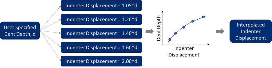
This first case shows how the scalability of the cloud, together with automation, can be leveraged to perform a precision dent assessment. Such an assessment would typically take days to solve with traditional methods but can be solved within an hour using the power of distributed cloud-computing. In practice, dents are often measured long after the indenter is removed, which provides operators with little-to-no information on the dent formation process.
This is mainly because the recorded dent depth includes some elastic recovery (springback). Additionally, if the dent is measured while the component is pressurized, the internal pressure can partially reround the dented region, further reducing the apparent depth and making the dent appear less severe than it truly is. To accurately assess an asset based on this measured damage, the indenter depth that produces a post-springback dent matching the measured value must be determined. This is traditionally done through serial iterations – repeatedly adjusting the indenter depth and re-running the FEA, leading to significant time and computational expense.The Dent FEA tool overcomes this, leveraging cloud scalability to deliver accurate results in under an hour, in most cases. The iterative process is parallelized (Figure 5) and multiple simulations with varying indenter depths run concurrently on separate virtual machines. The results are then used to establish the nonlinear relationship between indenter depth and final dent depth. Using this relationship, the appropriate indenter depth can be interpolated from the measured dent depth. By fully automating and parallelizing the process, the Dent FEA tool removes a major bottleneck in analysis, enabling analysts to focus on decision-making rather than computational overhead.
From Field to Finite Elements: Standardized Data Mapping
A persistent challenge in Level 3 assessments is the accurate and consistent representation of real-world damage data within a finite element model. In traditional workflows, this critical task—mapping field measurements onto the FEA mesh—is often performed manually and left to the analyst’s discretion. As a result, outcomes can vary significantly between analysts and assessments, introducing uncertainty and limiting reproducibility.
The FEA Suite addresses this challenge by automating the data mapping process. By integrating field data directly into the model setup in a standardized and repeatable way, the tools ensure input geometry and material distributions are handled with consistency and precision, improving the overall robustness of the simulation.
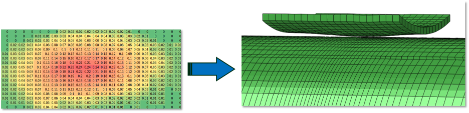
For example, the Dent FEA tool offers several standard indenter shapes, including ellipsoidal, cylindrical, spherical, and torus, which are suitable for many common damage scenarios. For more complex or non-standard dents, users can input the measured dent geometry directly in the form of a surface grid (e.g., deformation data over a 2D mesh in the axial and circumferential directions). The tool then constructs a custom indenter that conforms to this data, allowing for the simulation to closely replicate the actual field measurements (Figure 6). The indenter shape is created by using kriging interpolation, eliminating any spurious noise in the data entered by the user.
The Tank Settlement FEA tool also takes advantage of standardized data mapping, automating the integration of ground settlement profiles into axisymmetric FEA models of aboveground storage tanks. In field practice, bottom settlement is typically recorded at discrete radial locations, often with denser measurements near the critical edge regions, resulting in sparse and non-uniform datasets. Translating this data into a continuous settlement profile suitable for FEA requires interpolation, and the selected interpolation method can significantly influence the stress distribution, fatigue life prediction, and flaw assessment results. For example, conventional cubic spline interpolation can introduce artificial inflection points or “kinks,” which may exaggerate stress concentrations and lead to overly conservative assessments.
To address this, the automated Tank Settlement FEA tool offers three built-in interpolation schemes – cubic spline, monotonic spline, and B-spline – giving users transparent control over the mapping technique while eliminating analyst-to-analyst variability. This standardization ensures that the input data is interpreted consistently across assessments, reducing both uncertainty and conservatism while preserving the integrity of the underlying measurements.
Data mapping is also a key aspect of local thinning assessments. The positioning of the thin area relative to structural discontinuities, the resolution (mesh size) of the thickness profile to use in the analysis, and the relative positioning of multiple local thin areas all have a significant effect on the results of the analysis. In traditional analysis, a mesh is generated based on the discretion of the individual analyst and the readings are then mapped onto a manually chosen node set, which introduces variability.
The Thinning FEA tool addresses this challenge with an automated, consistent approach. First, it applies wavelet decomposition to the measured thickness data to identify the dominant spatial features, which then informs the appropriate mesh resolution. A structured rectangular mesh is generated in the thinned region to ensure uniform sampling of the thickness profile, eliminating inconsistencies introduced by manual node selection. Additionally, the tool automatically places the thin region with respect to nearby geometric discontinuities, ensuring that the modeled configuration accurately reflects measured distances in the field. This end-to-end automation minimizes analyst bias while preserving the fidelity of real-world data in the FEA model.
Uncovering the Ground Truth: Edge Settlement Analysis
The conventional method for assessing bottom settlement in aboveground storage tanks via FEA typically involves applying the measured settlement profile directly as a prescribed displacement boundary condition at the bottom of the tank. Although this approach is widely used, it has several significant limitations. It assumes continuous contact between the tank bottom and the ground, ignores the elastic behavior of the foundation, and does not allow for realistic movement of the tank floor between full and empty conditions. These assumptions do not represent physical reality and can lead to overly conservative results.
To address these shortcomings, the Tank Settlement FEA tool follows an improved, physics-informed workflow specifically designed by the experts at Equity Engineering. When users select the edge-settlement analysis option, the tool explicitly models the contact interaction between the tank bottom and the foundation. The underlying soil is simulated using a foundation stiffness model composed of axisymmetric elements supported by vertical springs (Figure 7a). To capture the heterogeneous behavior of the ground, the model allows the user to define different stiffness values in different radial regions.
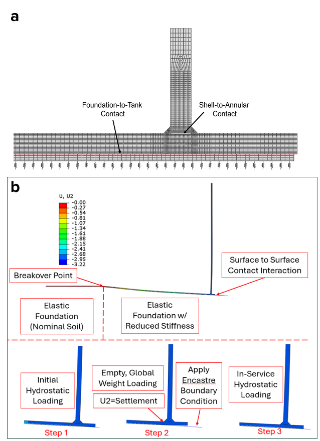
The FEA is conducted using a three-step procedure (Figure 7b):
- Full tank condition: A full hydrostatic load is applied with the foundation model in place.
- Tank emptying: The hydrostatic load is removed while fixing the foundation displacement, simulating tank springback.
- Operating load: The operating hydrostatic load is applied for the actual evaluation.
This three-step analysis offers a more realistic representation of the tank’s response to ground settlement, accounts for elastic rebound and contact loss, and avoids the overly stiff constraints imposed by fixed displacement boundary conditions. However, a key challenge remains – ground stiffness is rarely measured directly in the field. Instead, the edge settlement of the tank in the unloaded (empty) condition is typically recorded. Determining the ground stiffness that reproduces the measured settlement involves solving an inverse problem, which is inherently nonlinear due to the contact behavior and elastic recovery of the tank. This would traditionally require a time-consuming, serial iterative approach: analysts would manually adjust the stiffness value and re-run the first two steps of the procedure until the model-predicted edge displacement matches the field measurement.
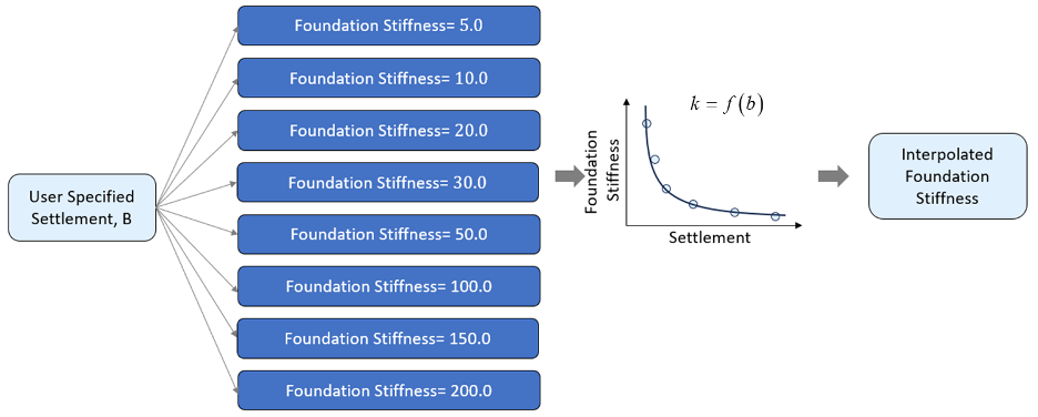
The Tank Settlement FEA tool automates this process using cloud scalability. It launches multiple instances of the simulation in parallel, each with a different assumed foundation stiffness to explore the relationship between stiffness and edge-settlement (Figure 8). Similar to the method used for inverse modeling in the Dent FEA tool, a nonlinear interpolation is used to estimate the foundation stiffness that results in an edge settlement close to the measured value. Through automation and cloud computing, an analysis which would otherwise take even an experienced analyst several days is performed in less than an hour.
Leaving No Mode Unturned: Buckling Assessment
The Thinning FEA tool implements a nonlinear buckling assessment methodology aligned with the procedures outlined in Paragraph 5.4.3 of ASME BPVC Section VIII, Division 2. In this approach, external pressure and any applicable supplemental loads (e.g., weight, thermal) are applied to the finite element model and a linear eigenvalue buckling (perturbation) analysis is performed to determine the critical mode shapes. The first mode shape is then scaled based on code-specified shell tolerances and applied to the idealized mesh as a strain-free geometric imperfection. This perturbed geometry is analyzed in a nonlinear elastic-plastic simulation, where the external pressure is incremented until the model approaches a numerical instability. The corresponding instability pressure, when divided by the code-prescribed safety factor (1.67), yields the MAWP for the thinned component.
While this method is well-established, it implicitly assumes that distortion resembling the first mode results in the lowest instability pressure. In practice, however, this is not always the most critical scenario. Though higher-order modes generally require greater pressure to initiate buckling, combinations of mode shapes can interact in non-obvious ways, leading to localized distortions that result in an instability at a load smaller than what the first mode alone would predict. To account for this, advanced assessments often involve applying composite mode shapes (i.e., various combinations of the first n modes) as initial imperfections. However, this approach quickly becomes computationally expensive. For n modes, there are 2n – n unique combinations to evaluate, each requiring a full, nonlinear FEA simulation. Limited by solver licensing, hardware constraints, and manual setup overhead, traditional desktop-based FEA workflows rarely support such extensive evaluations, often forcing analysts to settle for a first-mode-only assessment.
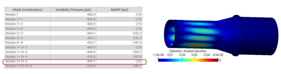
The Thinning FEA tool leverages cloud scalability and automation to overcome this limitation. It performs the nonlinear buckling assessment across all 12 unique combinations of the first four mode shapes simultaneously. These assessments are run in parallel across multiple virtual machines, dramatically reducing the analysis time and eliminating manual setup effort. As a result, analysts receive a robust and complete assessment in minutes.
For instance, in one representative case (Figure 9), the MAWP obtained from a composite mode shape was lower than that of the first mode, illustrating the importance of a comprehensive modal investigation. Remarkably, this entire workflow—including mesh generation, perturbation analysis, 12 elastic-plastic FEA runs, and post-processing—was completed in under 12 minutes, highlighting the transformative potential of cloud-based FEA for high-fidelity buckling assessments.
Discussion
Automation has long played a role in engineering analysis workflows, streamlining model creation, result extraction, and post-processing. However, the scope and impact of automation have historically been limited by two key constraints: computational resources and solver licensing models. Traditional FEA environments often tether automation to local hardware capacity, and licensing structures discourage parallelization or high-throughput simulations. As a result, even when automation scripts exist, their use has remained narrow and often relies heavily on manual intervention.
The tools described in this article represent a step-change in capability by combining automation with the cost-effective scalability of cloud computing. By decoupling FEA from fixed workstations and allowing compute-intensive tasks to be distributed across virtual machines, these cloud-native Level 3 tools enable analysts to perform more comprehensive and reproducible assessments in a fraction of the time previously required. Workflows that once took days or weeks can now be completed in under an hour—without sacrificing technical rigor.
Importantly, this transformation does not eliminate the role of the expert analyst. On the contrary, it amplifies their impact. Rather than spending time on repetitive modeling tasks that have been historical bottlenecks to the workflow, analysts can now devote more attention to interpretation, decision-making, and engineering judgment—areas where human expertise remains irreplaceable. The tools automate the mechanics of analysis, not the critical thinking that defines sound engineering.
That said, this technology is still in its early stages. While the current suite of tools demonstrates the feasibility and value of automating complex FFS assessments, there remains significant potential for growth. With further development, more damage mechanisms, geometries, and assessment workflows can be automated and made more accessible. Additionally, automated workflows can open doors to new analysis methods that have been avoided because they are unwieldy and prohibitively expensive in the traditional analysis paradigm.
As the field progresses, the balance between automation and engineering oversight will remain crucial. The goal is not to replace analysts, but to elevate the standard of analysis across the industry, making best-practice assessments more accessible, reproducible, and reliable. Cloud-enabled automation is not the end of the analyst’s role; it is the beginning of a new era in which advanced tools empower engineers to solve harder problems, faster and better than ever before.
Questions for the author? Submit the form below: