Introduction
Brazed aluminum heat exchangers (BAHXs) are plate-fin type heat exchangers that usually consist of tightly brazed corrugated aluminum plates [1]. Furthermore, they are commonly utilized in cryogenic fractionation and industrial gas processing because of their relatively high thermal efficiency, compactness, light weight, cost efficiency (with reasonable installation and operating costs), and overall favorable reliability characteristics. Specific BAHX applications include air separation, natural gas liquefaction, nitrogen rejection, natural gas liquids recovery, ethylene production, hydrogen recovery, and propane dehydrogenation [2,3]. The ability of BAHXs to accommodate multiple process streams (in some cases up to a dozen or more) permits process integration in air separation processes and other cryogenic systems. Additionally, the relatively large surface area per unit volume is particularly advantageous when low temperature process stream differences exist. Such applications are typically found in cryogenic systems and hydrocarbon dewpoint control systems where temperature difference is generally a function of compressor power [3]. In addition to providing an overview of BAHX applications and functionality, this article will provide a high-level overview of characteristic reliability and maintenance issues associated with operating BAHXs and practical damage mitigation techniques.
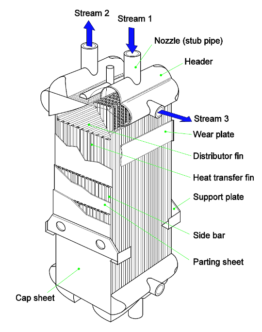
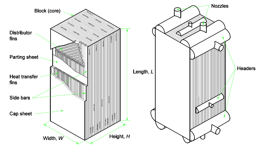
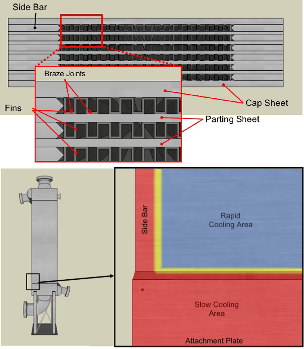
In general, brazed aluminum plate-fin heat exchangers consist of a block (core) of alternating layers (passages) of corrugated fins. The layers are separated from each other by parting sheets and sealed along the edges with side bars. Additionally, they are outfitted with inlet and outlet ports for the process streams. The block is bounded by cap sheets at the top and bottom. A simple illustration of a multi-stream plate-fin BAHX is shown in Figure 1. Another image that delineates the different components of a typical BAHX (and provides distinctive part nomenclature) is presented in Figure 2 [3,4]. The stacked assembly is brazed in a vacuum furnace to become a rigid core. To complete fabrication of the heat exchanger, headers with nozzles are welded to the side bars and parting sheets adjacent to the ports [3]. While BAHXs can offer years of useful service, they are distinctly prone to several damage mechanisms, including thermal fatigue [5,6], that will be elucidated further in this article. To this end, the lifespan of a BAHX remarkedly depends on the care with which a unit is operated and maintained throughout its service life, especially with respect to operating metal temperature gradients and process contaminants. BAHXs that have been operated attentively with respect to implementing recommended operating and maintenance guidelines can have service lives of 40 years or more, while poorly controlled processes can cause a heat exchanger to fail during initial unit start-up. Some BAHX fabricators have found that the typical industry expectation for useful BAHX service life is approximately 20 years [7]. The majority of BAHXs are eventually retired from service due to leaks attributed to plugging, fouling, cleanliness issues, thermal stress/fatigue cracking damage, ice formation, or hydrate accumulation. As such, keeping BAHXs clean and dry and avoiding harmful thermal gradients reflects key best operating practices intended to maximize equipment life [1,7]. Moreover, pragmatic and beneficial BAHX lifecycle management strategies will be briefly outlined herein.
Guide to Thermal Fatigue Management
Download the e-book
BAHX Industry Failures
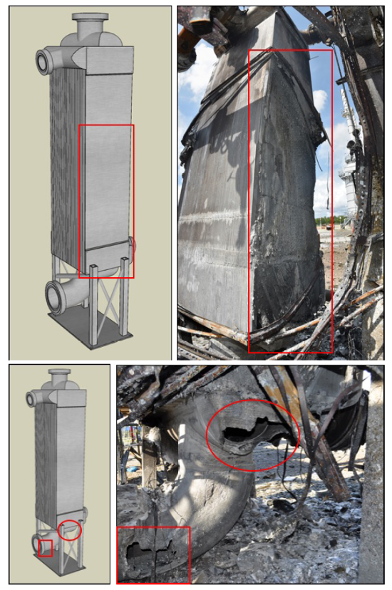
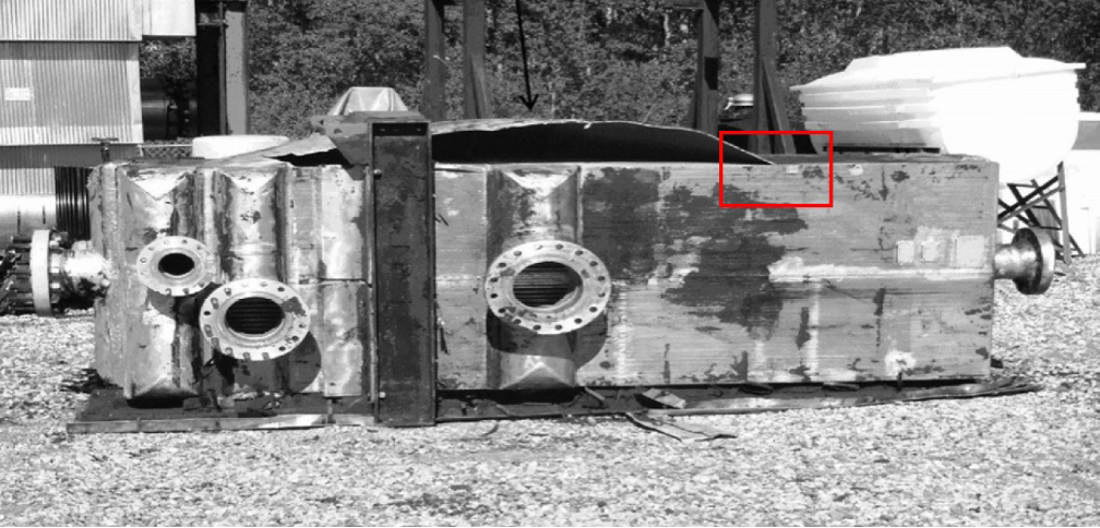
On June 27, 2016, a failure of a BAHX and a corresponding major loss of containment resulted in the release of methane, ethane, propane, and several other hydrocarbons at the Enterprise Products Pascagoula Gas Plant in Pascagoula, Mississippi [8]. The hydrocarbons ignited, initiating a series of fires and explosions that ultimately shut down the site for almost six months. Two workers were on the night shift when the incident occurred and were fortunately uninjured. As described in the Chemical Safety Board (CSB) failure investigation report, the probable cause of this incident was the rupture of a BAHX due to thermal fatigue [8]. Two process streams were running through this BAHX at the time of failure. The warm stream consisted of feed gas, while the cooler, liquid stream originated from a demethanizer column. Figure 3 shows post-incident photographs of rupture locations in the failed BAHX system. Specifically, the top image in Figure 3 highlights the believed location of the initial loss of containment (the north cap sheet and portions of several fin layers). The bottom image shows two rupture locations, one in the header and another one in the piping connected to the header. These locations are believed to have failed after the initial hydrocarbon release from the cap sheet region. In this instance, the absence of a reliable procedure (e.g., understanding the effect of metal temperature fluctuations) to ensure the mechanical integrity of the heat exchanger contributed to the catastrophic failure. In general, thermal fatigue commonly forms small cracks in BAHXs. These small cracks can coalesce and ultimately develop into measurable hydrocarbon leaks that can typically be repaired with minimal expense or consequence before a major loss of containment or catastrophic rupture occurs. Nevertheless, this June 2016 incident, as well as four other recent documented BAHX failure events (discussed below), illustrate that the reliance on a leak-before-failure assumption is generally not appropriate for BAHXs. In this particular case, the ensuing failure investigation indicated that instead of assuming that small leaks will always precede larger ruptures, operators of midstream gas plants must assess and manage the risk of sudden and catastrophic BAHX rupture scenarios where thermal fatigue plays a significant contributing role. For perspective, more than 500 similar gas processing facilities are in operation across the U.S., and cryogenic separation using BAHXs is relatively common [8].
A post-incident laboratory examination of the failed BAHX revealed clear evidence of service-related thermal fatigue damage at several locations that accumulated over the 17-year operating history of the unit. Based on this metallurgical investigation, as well as process data and physical evidence, the CSB concluded that thermal fatigue cracking was the root cause of the failure, which allowed process fluids in active passes (layers) to leak into blocked passes and weakened brazed joints between fins and parting sheets [8]. Available evidence eliminated several other well-known potential damage mechanisms (explained below). The most likely failure scenario involved leakage of process fluids into the outer layers of the exchanger due to thermal fatigue cracking. These outer layers were consequently blocked (likely due to an inadequate repair weld of several layers) with no relief venting after a previous repair for thermal fatigue-induced cracking damage. As such, the outer regions of the BAHX became over-pressurized and catastrophically ruptured (at the cap sheet). In summary, the key steps that ultimately caused the failure of the BAHX cap sheet are as follows [8]:
- The existence of blocked layers within the exchanger
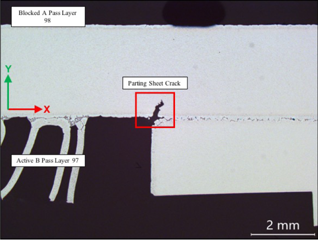
- The development of thermal fatigue cracks in the parting sheet adjacent to the blocked layers (see Figure 4)
- The separation of at least one layer from the core of the exchanger
- The expansion of the accumulated fluid in the blocked layer due to heating
- The absence of venting or draining to allow the accumulated fluid to readily escape from the blocked layer
The CSB investigation report for this 2016 failure [8] also documents four other BAHX failures. These failures, attributed at least partially to thermal fatigue cracking, are briefly summarized as follows:
- May 2015 – A ConocoPhillips gas plant BAHX (installed in 1994/1995 and repaired in 1998 and 2000) ruptured and released hydrocarbons to the atmosphere. The cap sheet of this exchanger bulged from the core after a failure of the brazed joint (likely driven by thermal fatigue cracking) between the fins and a cap sheet (see Figure 5).
- August 2012 – After 17 years of service, a BAHX ruptured at Enterprise’s Chaco Gas Plant. Before the incident, the exchanger had experienced inter-pass leaks, but not external ones. A subsequent metallurgical evaluation of the exchanger concluded that a mechanical overload caused the brazed joints to fail, but it did not identify the initiation site of the failure; it is suspected that thermal fatigue cracking played a role in initiating the failure.
- 2006 – A BAHX at another gas plant ruptured and one of the cap sheets separated from the core, from top to bottom. After examining the exchanger, the exchanger fabricator indicated that no definitive failure mechanism could be identified, but severe fin cracking and thermal fatigue were determined to be likely contributing factors.
- April 2014 – A BAHX failure occurred in a process unit at an Opal, Wyoming gas processing plant, which had been in operation since 1999. The exchanger had two cores welded to one another (differs from the common single-core configuration). It is suspected that process fluids leaked into the enclosed area after the intermodal space between the two cores pressurized. Nearly the entire core-to-core weld seam cracked and ruptured. The post-incident metallurgical investigation ruled out several potential failure modes, noting that while direct evidence of thermal fatigue was not identified, it could not be strictly eliminated as a probable cause.
The Influence of Thermal Gradients
Aluminum alloys, which exhibit superior tensile strength at cryogenic temperatures compared to typical carbon steels, have one significant disadvantage – they can be relatively susceptible to fatigue cracking and failure [9]. If a BAHX has been properly designed, the temperature difference between process streams and any internal exchanger metal temperature gradients will not normally result in overly harmful thermal stresses. However, if any process stream experiences a variation in flow rate, temperature, or composition, the amount of heat transfer will fluctuate, and metal temperature differences may become more severe and thus more damaging. In general, the different portions of a BAHX (fin matrix, parting sheet, side bars, etc.) are tightly connected, each with varying thicknesses. The thicker aluminum parts change temperature more slowly than the thinner ones, and if the rates are sufficiently different, the expansion and contraction can be disproportionate. This induces elevated stresses on the connections within the BAHX as the aluminum parts push into and pull apart from each other. Over time, this cyclic tensile and compressive behavior strains the metal and creates thermal fatigue cracks that can detrimentally permit process fluids to leak into the atmosphere or between adjacent layers within the exchanger. Additionally, thermal shock is a severe form of thermal fatigue cracking that occurs when notable and non-uniform thermal stresses develop over a relatively short time due to differential expansion or contraction. Thermal shock is typically associated with a colder fluid contacting a warmer metal surface. Thermal fatigue and thermal shock can also influence the fin matrix in a BAHX when it accumulates to the point that the braze joints between the fins and the parting/cap sheet weaken and eventually fail. This causes the forces/stresses on adjacent joints to increase, and if the joints are unable to sustain the added load, they may fail as well, causing a chain reaction that ends with a sudden rupture of the exchanger pressure boundary. While this behavior may cause a reasonably small, detectable leak, in many cases unpredictable and catastrophic rupture can ensue in certain circumstances, as highlighted in the failures described above. Figure 6 depicts a region in BAHXs that generally exhibits particular thermal fatigue damage proclivity; that is, the side bar/attachment plate junction with the cap sheet (notice the thickness mismatch). In this figure, the thicker pieces of aluminum (e.g., the side bar and attachment plate [red]), change temperature at a slower rate than the thinner cap sheet (blue). Adding and removing thermal stresses where these pieces merge (yellow region) can eventually cause thermal fatigue cracks to initiate and propagate to an unstable size [8].
Improper management of thermal gradients can lead to the development of thermal stresses and may lead to eventual cracking. Due to complex flow patterns and compact design/internal layout of most BAHXs, it is often difficult to determine local temperature gradients between individual process streams and between one stream and the exchanger wall itself. Hence, invoked differential temperature limits are usually based upon inlet and outlet temperatures as measured from process temperature indicators. To minimize thermal fatigue in BAHXs, several industry guidance documents recommend limits for maximum cyclic temperature fluctuations during operation and rates of cooling or heating during both start-up and shutdown operations. Nonetheless, numerous midstream gas plant operators have reported that these limits and rates may not be realistic, indicating that further dialogue between equipment manufacturers and operators would be beneficial. The desire by midstream gas plant operators to keep process data confidential, in conjunction with the “low frequency, high consequence” nature of catastrophic failure of BAHXs, has hindered industry-wide examination and learnings as they relate to BAHX life expectancy [8]. In critical applications, thermal-mechanical fatigue analysis may be warranted to estimate remaining life and establish reasonable inspection intervals [5,6].
Other BAHX Damage Mechanisms
BAHXs can handle a wide variety of process fluids in many different types of applications. In general, process streams need to be clean, dry, and non-corrosive to aluminum. Trace impurities of H2S, NH3, CO2, SO2, NO2, CO, Cl, and other acid-forming gases do not usually create a corrosion problem in streams with water dewpoint temperatures lower than the cold-end temperature of the BAHX. Chemical attack may be a concern if elevated levels of chlorides, amines, acids/bases, or cleaning agents are present in the process stream [7]. Under certain conditions, mercury can corrode aluminum and therefore caution must be exercised when handling mercury-containing process fluids; however, there are many instances where BAHXs have been successfully utilized with fluids containing mercury, provided that suitable equipment design and operating procedures are implemented [3]. Amalgam corrosion is a damage mechanism affecting aluminum from the contact of liquid mercury breaching the surface oxide layer. This damage mechanism requires the presence of liquid water and, therefore, the susceptibility and rate of amalgam corrosion penetration are directly proportional to the humidity. Furthermore, since the mercury itself is not consumed during the amalgamation corrosion reaction, this damage mechanism is self-propagating. Additionally, the amalgam corrosion reaction is not alloy-specific, and all aluminum alloys can be detrimentally affected. In many cases, where mercury deposits exist in discrete and non-continuous limited space and liquid water is present, amalgam corrosion can be localized in the form of pitting (sometimes severe). These pits are often known to propagate when the exchanger is relatively warm (equipment maintenance or unit shutdown) and in low areas that may have surface mercury contamination. Also, liquid metal embrittlement (LME) is a cracking damage mechanism where certain molten or liquid metals come in direct contact with specific alloys, often with cracking that is sudden and brittle in nature [10,11]. In the context of a BAHX, LME refers primarily to the presence of liquid mercury in contact with a susceptible metallurgy. High-strength aluminum alloys that contain magnesium as a primary alloying addition, such as Alloys 5083 and 6061, may promote the formation of metallurgical features that are potentially susceptible to LME.
Additionally, fouling can occur due to the solidification of contaminant compounds in the stream, which tend to coat the heat transfer surfaces. Typical sources of fouling include hydrates, heavy hydrocarbons, waxy materials, and compressor oils. A common method to prevent fouling is to monitor stream compositions and/or purity directly upstream of a BAHX to detect for contaminants, and if detected, remove all contaminants before entering the exchanger. If a BAHX has become fouled, chemical cleaning is often necessary. The cleaning agent should be selected based on the specific fouling compound and must be safe for use with the aluminum alloy in question. Specialized cleaning contractors with experience cleaning BAHXs are always preferred [3]. In addition, plugging occurs when the passages inside the BAHX become obstructed, typically with foreign particulate matter or debris. A larger-than-normal drop in pressure or temperature differential between adjacent streams may directly indicate that fouling or plugging is present in the exchanger [7]. Furthermore, a deviation from specified pressure drop limits may indicate a deviation of thermal gradients considered in the original design basis. From a reliability perspective, the main issue associated with plugging and fouling is generally maldistribution of flow, not necessarily pressure drop. Flow maldistribution can lead to an imbalance of flow and temperature profiles, creating a potential for excessive thermal stresses as evidenced by inadequately preheated streams at the warm end of the BAHX and inadequately cooled streams at the cold end, both of which increase the local thermal stresses at these areas. Local increases in fluid velocity in a particular plugged stream may lead to erosion of the thin, internal fin attachments and gradual or rapid deterioration of the protective aluminum oxide scale. Proper filters (usually mesh filters) must be installed upstream of the heat exchanger system and maintained according to the filter manufacturers’ recommendations to prevent plugging from particulates such as pipe scale or molecular sieve dust. If a BAHX is inadvertently plugged, proven and widely accepted cleaning procedures are available [3].
Excessive ice formation, hydrate (substances containing water that form snow or ice-like crystals at certain temperature and pressure regimes) accumulation, and even CO2 ice materialization can increase pressure drop, deteriorate thermal performance, and cause flow maldistribution, thus leading to higher thermal stresses. Ice formation is caused by streams with water content that is high enough to freeze inside the BAHX during operation (streams with high dew point). It is also caused by residual liquid water in the BAHX or in upstream piping and equipment that is fed into the unit and not properly purged prior to unit start-up [7]. Fin rupture due to ice expansion occurring in layers near the outside of the BAHX may create visible bulges in the cap sheets. If the fin rupture only occurs internally to the BAHX, then the bulges will be fully inside the BAHX and not visible from the outside. Furthermore, ice formation can be prevented by continuous dew point monitoring of stream inlets and a properly functioning dehydration system. If ice formation is detected before it has ruptured any fins, it can be dissolved by alcohol injection or de-riming procedures [7].
Recommended BAHX Design and Operating Practices
In general, establishing integrity operating windows (IOWs) for BAHXs is recommended. IOWs are defined as established limits for process variables or parameters (chemical and physical) that can influence the integrity of equipment if the process operation deviates from the specified limits for a predetermined amount of time [12]. Furthermore, IOWs are generally classified into different levels (e.g., critical, standard, informative) distinguished by risk to set priorities on notifications (e.g., alarms, alerts) and timing of actions to be implemented when IOWs are exceeded. Typical, technically based IOWs for BAHXs include limits on mercury content of feed, thresholds for temperature differences between process passes, and upper boundaries for pressure drop across different passes, among others. Several good engineering design, inspection/monitoring, and process operating practice considerations to maximize the longevity of BAHXs are outlined below [13].
Thermal-Mechanical Design
- Simplify the piping to and from the BAHX as much as possible, minimizing horizontal runs, reducers, manifolds, and other piping elements that contribute to piping pressure drop and potential unstable two-phase flow.
- Design nozzles and piping for self-venting flow and design lines to prevent slug flow.
- Minimize pressure drop in the riser (return) piping.
- Design condensing streams to be free draining (away from the heat exchanger).
- Ensure proper flow distribution into the heat exchanger, including but not limited to manifolds and header design (consider all operating conditions, including start-up, shutdown, recovery/rejection, Joule-Thomson expansion, dew point control, etc.).
- Mitigate the effects on thermal performance at low process flows (e.g., start-up conditions).
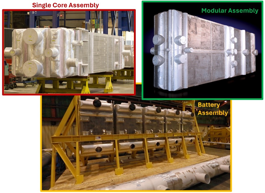
- Consider the overall damage tolerance of single core, battery (multiple cores not welded together), or modular (multiple cores welded together in one assembly) assembly configurations and their ability to mechanically handle cyclic, transient, and reversible operation conditions (see Figure 7). In general, modular configurations are directionally more susceptible to thermal shocks during transient conditions than single core and battery configurations, unless specifically designed by the BAHX manufacturer to operate at these conditions.
- Inter-modular layers (the layer located between two separate cores welded together) require a vent and a drain, where appropriate. Blocking the inter-modular layer vent/drain (sometimes occurs during weld repairs) may create an unrated pressure vessel with additional hazards to consider. For cores installed inside a cold box, the inter-modular and dummy layers may be vented within the cold box with relief protection and leak detection for gases lighter than air.
Contaminant Removal
- Incorporate comprehensive dehydration systems in inlet gas process streams and ensure appropriate contaminant removal – specifically, pollutants (in concentrations greater than trace amounts) such as mercury, SO2, Cl and NOX can be extremely corrosive to aluminum alloys.
- Consider mercury tolerant heat exchanger features and install mercury removal beds utilizing adsorbent material – regenerative and non-regenerative options exist.
- In general, BAHXs should not be operated in environments where mercury concentrations are greater than 12.2 pptv (0.1 μg/Nm3). Above this limit, mercury guard beds and mercury tolerant features should be employed. Current mercury guard technology can achieve favorably low mercury concentrations of around 1.22 pptv (0.01 μg/Nm3).
- Below -37.8°F (-38.8°C), mercury is a solid and generally not a concern. BAHXs are most susceptible to mercury attack when warmed and opened to the atmosphere for maintenance. Accumulated liquid mercury in the presence of water can cause severe corrosion to aluminum due to the creation of an aluminum amalgam. Vaporous mercury is not usually a structural concern for aluminum alloys.
- Utilize inlet strainers for the entire life of the heat exchanger, not just at start-up. Strainers should be sized properly for the flow rate with minimum pressure drop, and filtration should remove particles larger than 177 microns (80 Mesh Tyler Standard) at a minimum.
- Consider an active monitoring/maintenance program to accurately measure and record the pressure drop across the strainer and routinely clean/replace as required.
Operating/Monitoring Procedures
- Measure leakage flow through inter-modular pass (dummy layer) vent/drain.
- Monitor the differential pressure across each pass of the heat exchanger to identify erratic flow conditions.
- Monitor exchanger approach temperatures to determine fouling rates.
- Employ methanol usage to prevent hydrate or ice formation and ensure operating temperatures remain warmer than the freezing point of methanol.
- Consider flow controls to mitigate low-flow and no-flow operation in adjacent streams.
- Set process and deviation alarms for pressure drop, process temperature, and flow rates.
- For a typical BAHX geometry under steady state conditions, the maximum permissible temperature difference between streams should be approximately 90°F (50°C). In more severe cases such as two-phase flows, transient, and/or cyclic conditions, the temperature difference between streams should generally be lower, typically 36°F to 54°F (20 to 30°C).
- In general, limiting cyclic or frequently repeated temperature fluctuations of any stream to ±1.8°F (±1°C) per minute during steady-state operation is recommended.
- During warm-up/cool-down (or when switching operational modes), a temperature change rate of 3.6°F (2°C) per minute maximum, not to exceed 108°F (60°C) in an hour, to allow for gradual dimensional adjustments is often suggested. This recommendation can also effectively prevent thermal shock. Additionally, temperatures should be acquired at suitable locations on the exchanger.
Inspection Considerations
- Consider visual inspection on a routine basis to identify any obvious damage or maintenance issues.
- Perform routine leak detection utilizing forward-looking infrared (FLIR) surveys on BAHX reboilers, those in sub-cooler service, and those configured with inter-modular layers. Leak detection should be employed following any notable plant events or operating excursions, including compressor trips, start-ups, shutdowns, dehydrator bed switching, etc.
- Periodically perform phased array ultrasonic testing (PAUT) of heat exchanger header welds to identify the presence of crack-like flaws.
- Consider inspecting BAHX headers using a borescope or employing dye penetrant examination of welds such as header-to-core welds, nozzle-to-header welds, inter modular core welds etc. (note that this is not an acceptable test method for brazed surfaces).
Summary and Conclusions
BAHXs are widely utilized in the industrial gas processing, cryogenic fractionation, and petrochemical industries, among others. While they offer many distinct advantages such as favorable heat transfer characteristics and compactness, it is imperative for plant reliability and maintenance personnel to understand the damage mechanisms that most often afflict BAHX components. Specifically, thermal fatigue, amalgam corrosion due to mercury contamination, and possible liquid metal embrittlement are worth noting. Operating conditions that promote fouling or plugging can be especially damaging and can dramatically intensify pressure drop and increase the propensity for flow maldistribution. Being able to identify and mitigate these common damage mechanisms and disadvantageous operating scenarios is the key to ensuring long-term safety and reliability of BAHXs. Contaminant filtration and functioning dehydration systems represent critical aspects of achieving dependable BAHX operation as well. Establishing appropriate IOWs and routinely monitoring different process conditions such as process temperature fluctuations, pressure drop, mercury content, etc., are consequential pieces of a robust mechanical integrity program for BAHXs. Furthermore, it is recommended to consistently inspect known problem areas and crucial welded regions or junctions for severe damage (e.g., crack-like flaws) and perform leak detection (especially following any process upsets) to manage overall risk. While BAHXs may sometimes fail via small cracks that lead to measurable leaks, it is important to recognize that catastrophic ruptures are also possible under certain conditions, as highlighted herein. Lastly, designing, inspecting, and operating BAHXs in accordance with industry best practices serves as the first line of defense against significant and costly premature component failures.
If you have any questions for the author, please submit the form below:
References
[1] Shields, P., “Best Practices for Brazed Aluminum Heat Exchangers - Guidelines for Optimum Performance and Longevity,” Business & Industry Connection (BIC) Magazine, Nov. 14, 2017.
[2] Hussain, I., “Safely Design Brazed Aluminum Heat Exchangers to Avoid Thermal Shock,” Gas Processing and LNG, Nov. 30, 2020.
[3] ALPEMA, “The Standards of the Brazed Aluminum Plate-Fin Heat Exchanger Manufacturers’ Association (ALPEMA),” ALPEMA, 3rd Ed., May 2012.
[4] API, API Standard 668, “Brazed Aluminum Plate-Fin Heat Exchangers,” First Ed., November 2018.
[5] Prueter, P.E., “A Guide to Thermal Fatigue Management,” eBook, Inspectioneering LLC, https://inspectioneering.com/content/2021-05-13/9647/a-guide-to-thermal-fatigue-management, The Woodlands, TX, May 13, 2021.
[6] Prueter, P.E., “Fatigue-Life Assessment,” Chapter 5 in Failure Analysis and Prevention, ASM Handbook Vol. 11. ASM International, Materials Park, OH, 2021.
[7] Chart Industries, “BAHX Product Bulletin,” Issues 1 – April 2016, Chart Industries.
[8] CSB, “Case Study - Loss of Containment, Fires, and Explosions at Enterprise Products Midstream Gas Plant,” U.S. Chemical Safety and Hazard Investigation Board, No. 2016-02-I-MS, Washington, D.C. 2019.
[9] Swain, R.D., and Miller, A.C., “Aluminum Plate-Fin Heat Exchanger Thermal Fatigue Study,” AIChE Paper Number: 38c, Prepared for Presentation at the 2011 Spring National Meeting Chicago, IL, March 14 – 17, 2011.
[10] Dobis, J.D., Cantwell, J.E., and Prager, M., “WRC Bulletin 489 (2nd Edition): Damage Mechanisms Affecting Fixed Equipment in the Refining Industry”. 2019. The Welding Research Council. Shaker Heights, Ohio.
[11] API, American Petroleum Institute, API Recommended Practice 571 – Damage Mechanisms Affecting Fixed Equipment in the Refining Industry. 3rd Edition, 2020. American Petroleum Institute. Washington, D.C.
[12] API, Recommended Practice 584, Integrity Operating Windows, American Petroleum Institute, Washington D.C., 2021.
[13] GPA, “GPA Technical Bulletin - GPA-TB-M-001: Brazed Aluminum heat Exchangers,” Gas Processors Association, Sept. 2015.