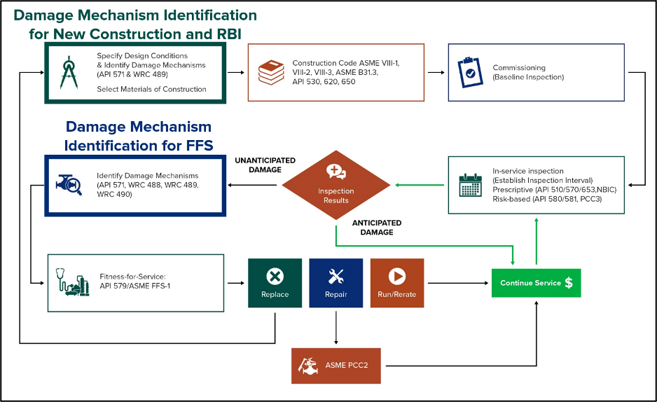
Industrial gas suppliers provide critical gases for numerous commercial sectors such as healthcare, energy, semi-conductors, food and beverage processing, and many other manufacturing applications. Specifically, gases such as nitrogen, oxygen, hydrogen, carbon dioxide, carbon monoxide/syngas, and argon (among others) are produced to meet a broad range of needs across these industries. Industrial gas suppliers generate these gases using several different processes, each requiring different types of pressure-retaining equipment such as pressure vessels, heat exchangers, tanks, process piping, and even fired heaters. Mitigating in-service damage and maximizing the long-term reliability of this pressure equipment is imperative to ensure plant safety and optimize production. Furthermore, achieving this requires a thorough understanding of different damage mechanisms that can detrimentally affect process equipment and implementation of a robust mechanical integrity program that leverages the concepts of risk-based inspection (RBI) and fitness-for-service (FFS). In fact, leveraging materials and corrosion experts for accurate damage mechanism identification and damage progression rate estimation represents the cornerstone of successful equipment design decisions, RBI programs, and FFS (remaining life) assessments. This assertion is highlighted in Figure 1, where the critical role of damage mechanism identification in all aspects of pressure equipment operating life is depicted.
A comprehensive summary of many different damage mechanisms, their typical morphologies, important factors influencing damage susceptibility/progression, and recommended mitigation strategies is provided in API 571, Damage Mechanisms Affecting Fixed Equipment in the Refining Industry [1]. While API 571 is generally specific to the oil refining industry, it provides detailed information on many damage mechanisms that are relevant to industrial gas suppliers. Additionally, API RP 580, Risk-Based Inspection [2], provides the minimum requirements and the corresponding basic elements for developing and implementing an RBI program. It also provides guidance for establishing inspection plans for fixed equipment in the refining and petrochemical industry. Specific details and calculation methods are not provided in API RP 580. As such, API RP 581, Risk-Based Inspection Methodology [3], provides specific details and calculation procedures for development of inspection plans for fixed equipment. The intent of these two documents is for API RP 580 to introduce principles and minimum requirements, while API RP 581 provides quantitative calculation methods and specific requirements to determine an inspection plan based on risk. This RBI methodology is anchored in the consequence of failure (COF) and probability of failure (POF) for a given application, with the latter being heavily dependent on the relevant damage mechanisms (and inspection effectiveness).
API 579-1/ASME FFS-1, Fitness-For-Service (API 579) [4] provides engineering assessment methods for qualifying different forms of equipment damage, with the ultimate goal being to help guide run-repair-replace decisions for damaged or potentially damaged in-service equipment. Specifically, FFS methods consistent with API 579 serve as a valuable supplement to RBI programs because time or cycle-dependent damage mechanisms (e.g., high-temperature creep, fatigue, etc.) that fall outside the bounds of conventional RBI can be formally evaluated and appropriate remaining life estimates can be established. FFS can be extremely valuable in safely extending the useful operating life of damaged equipment to minimize unit downtime and consequently mitigate lost production. In question-and-answer format, this article will summarize some practical damage mechanism considerations that can help form the basis of both comprehensive RBI programs and FFS assessments for industrial gas supplier pressure equipment, including steam methane reformers (SMRs) and air separation units (ASUs).
What are the Most Prevalent Damage Mechanisms Affecting SMRs?
SMR units are designed to generate hydrogen-rich synthesis gas by heating methane (from natural gas) with steam through the use of a catalyst. Potential damage mechanisms affecting different sections of SMR units are summarized in Figure 2 and Table 1. Some of these damage mechanisms (the ones highlighted in Table 1) are not covered with conventional RBI and as such, FFS-based methods, material testing, or other engineering calculations are often necessary in these instances. Specifically, high-temperature creep [5], different forms of fatigue cracking [6], and material embrittlement (that can significantly degrade fracture toughness) usually necessitate more detailed analysis on a case-by-case basis. Table 1 reflects general damage characterizations. Damage progression rates can vary from one unit to another. As such, materials and corrosion experts should evaluate specific process units and plants based on materials of construction, historical operating conditions, and inspection histories.


Additionally, a less recognized damage mechanism, which is well-known to materials experts and those involved in SMR design, is CO2 corrosion in dead legs. For instance, in the high-temperature shift section where water condenses, CO2 dissolved in the water phase can form carbonic acid, leading to CO2 corrosion. Furthermore, some plants have experienced repeated failures in the inlets of safety valves that were dead legs. In general, it is critical that these dead legs be properly traced, insulated, and monitored, especially in colder environments. Poor insulation conditions can lead to water condensation, triggering CO2 corrosion. Furthermore, CO2 corrosion often leads to localized pitting corrosion that can progress rapidly if not addressed. Maintenance becomes crucial in these scenarios. To this end, insulation and heat tracing of dead legs need to be regularly monitored and repaired promptly if damaged. The corrosion rates can vary, but can reach 25 to 50 mils per year or higher, depending on factors like pH and operating temperature. Ultimately, proactive maintenance is key to preventing leaks and ensuring the integrity of the system. While corrosion and materials experts are familiar with this mechanism, it is not always fully appreciated until it causes operational issues or failures.
Are There Any Practical Considerations for SMR Furnace Tubes?
SMR furnace catalyst tubes and outlet manifolds/pigtails are designed to withstand high temperatures in-service. In general, favorable properties required in construction material for high-temperature applications include resistance to oxidation, carburization, and corrosion as well as adequate mechanical strength, thermal fatigue strength, and creep-rupture properties at normal operating temperatures to maximize equipment longevity [7]. Carefully specified mechanical design features and weld details can also be beneficial for outlet manifolds and pigtails. SMR catalyst tubes usually operate at temperatures between 1,472°F and 1,832°F (800°C – 1,000°C) and are typically fabricated from HP-modified micro-alloys. Furnace outlet manifolds and pigtails are typically fabricated from Alloy 800H or Alloy 800HT since reformer product gases typically leave the furnace at temperatures ranging from 1450°F to 1580°F (790°C to 860°C) [8]. These high-temperature materials typically behave in a creep brittle fashion, so as creep strains accumulate over time, the material can lose its ductility (exhibit embrittlement) and become more prone to fracture failures. Evaluating these components and predicting remaining life falls outside the bounds of conventional RBI methodologies, and as such, the FFS concepts of API 579 [4] are required to evaluate their high-temperature behavior.
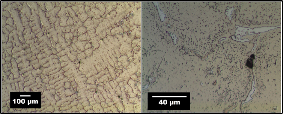
HP-modified cast tubular products are used extensively for SMR tubes, and many proprietary variants are produced today by numerous suppliers. In these materials, creep resistance and corrosion resistance are achieved through elevated Cr and nickel (Ni) content. The increase in nickel content is particularly important in stabilizing the austenitic grain structure and markedly improving the carburization resistance (silicon and aluminum are also known to mitigate the effects of carburization) [9]. The more pronounced nickel content directionally improves the cyclic material behavior, and as such, bolsters the adherence of protective oxide films and the thermal fatigue properties. Furthermore, HP-modified alloys characteristically contain less than 0.50% carbon, which facilitates the formation of chromium carbides that resist deformation at elevated temperatures. The inclusion of carbide-forming elements such as niobium, titanium, tungsten, cobalt, molybdenum, or others, is an essential step to further improve creep strength [9]. Figure 3 shows the microstructure of an ex-service HP-modified SMR tube. Characteristically for centrifugally cast austenitic material, a columnar structure is observed at the macroscopic level, and the microscopic appearance consists of a dendritic grain structure, with carbides and precipitates (some of which are as-cast and others which may be due to thermal aging) dispersed within the austenite matrix [5].
When it comes to predicting remaining creep life of SMR tubes, the Omega Creep Method as outlined in API 579 [4] can be leveraged. In certain cases, ex-service tube samples can be tested at elevated temperatures to accurately measure and quantify accumulated creep damage and to estimate tube remaining life. An example of creep strain rate behavior over time for an ex-service HP-Microalloy (25Cr-35Ni-Nb+Ti) tube specimen taken from an SMR is shown in Figure 4. The test conditions for this specimen were 1,875°F (1,024°C) at 3 ksi (20.7 MPa). In this case, the illustrated curve is dominated by tertiary creep, making Omega regression feasible and applicable. In general, for cases where tertiary creep is not observed at initial test conditions, temperature and/or applied stress may have to be adjusted to achieve desired creep strain trends as a function of time. Furthermore, this specimen was tested until rupture, which occurred just before approximately 800 hours at these constant test conditions; Omega creep tests are often not run to rupture, however, because sufficient strain rate behavior can be extracted before the onset of gross failure.
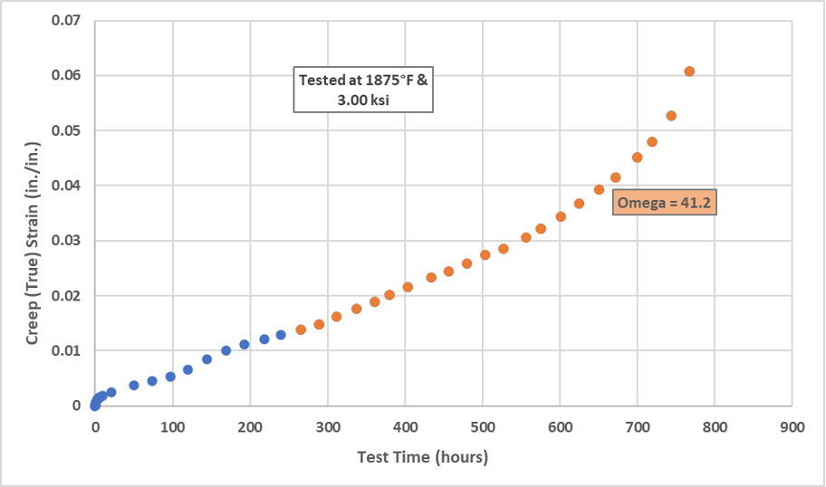
Figure 4: Creep Strain vs. Time for Ex-Service HP-Microalloy SMR Tube [5]
What Does a Remaining Creep Life Assessment Look Like for SMR Tubes?
E²G routinely performs detailed SMR tube remaining life calculations and can also perform Omega creep testing on tube samples when warranted. An example of thermocouple readings (outlet metal temperature) and inlet pressure data from SMR tubes as a function of time is shown in Figure 5. This type of data acquisition scenario and documentation (in this case over several years) is extremely valuable when attempting to estimate the remaining life of the tubes. The acquired data can furthermore be manipulated into a loading histogram that captures the historical distribution of operating data. This data can then be directly leveraged in FFS (remaining creep life) calculations (see Figure 6 for a histogram of the temperature data rendered in Figure 5). This type of loading history can be incorporated directly into E²G’s software packages that can accurately determine creep damage accumulation as a function of both pressure and metal temperature over time.
An additional advantage of automated software algorithms is that they afford analysts the ability to straightforwardly investigate sensitivity to input parameters such as tube thickness (e.g., corrosion rate), metal temperature, and pressure to account for unknowns in both operating conditions and material properties. Understanding prediction sensitivity to analysis inputs is an essential part of any FFS or remaining life assessment. E²G’s software programs have built-in parametric study and probabilistic analysis functions that offer analysts the ability to accomplish this in an expeditious and practical manner. Furthermore, running statistical analysis or parametric studies to quantify the overall effect of fluctuations in such inputs is always recommended because this can also provide valuable perspective on how the margin of error associated with acquired data can ultimately influence the assessment outcome. Moreover, acquiring and tracking process data represents a useful way to maximize the accuracy of remaining life calculations, which can in turn provide technical justification for extending equipment operating life. From an economic standpoint, having the technical justification to defer a retube of a SMR can be extremely beneficial.


Lastly, it is worth noting that there are currently two API documents under development that are intended to focus on SMR furnace material selection, fabrication, and inspection as well as catalyst tube reliability. They are API 561: Reforming Furnaces for Hydrogen and Synthesis Gas Production in General Refinery and Petrochemical Services and API Technical Report 942-C: Materials, Fabrication, Inspection and Repair Considerations for Hydrogen Reformer and Pyrolysis Furnace Tubes.
What are the Most Prevalent Damage Mechanisms Affecting ASUs?
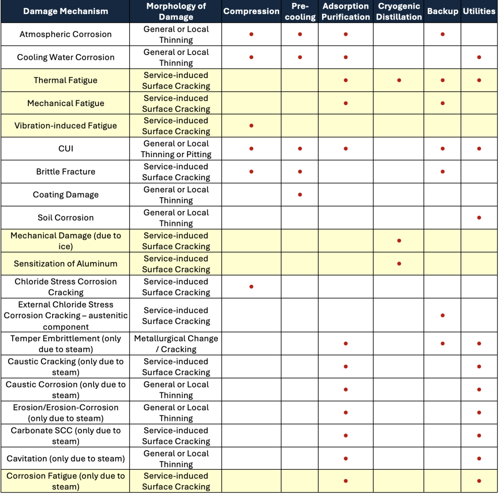
The process of air separation is typically carried out in three ways: membrane separation, pressure swing adsorption, or cryogenic distillation. These three separation techniques offer different benefits. Cryogenic distillation is the most common and generally the most cost-effective approach for air separation, especially if large quantities of gases are needed. Furthermore, it is the only method that can simultaneously recover nitrogen, oxygen, and argon in an efficient manner. Pressure swing adsorption notably introduces the possibility of mechanical fatigue damage (crack growth) in pressure equipment because of the frequent pressure cycles required during the adsorption process [10]. Table 2 is provided below to generally summarize relevant damage mechanisms afflicting different regions in ASUs. It is noted that damage mechanisms and corrosion rates should be reviewed and established by qualified specialists on a case-by-case basis. Again, the highlighted damage mechanisms in Table 2 are not usually included in the RBI methodology and often necessitate the use of FFS techniques, specialized inspection, or material testing.
Are There Any Other Materials and Corrosion Considerations for Industrial Gas Suppliers?
One often-overlooked damage mechanism is what some identify as “unspecified internal corrosion.” This type of corrosion, which is not explicitly covered in API 571 [1] or API 581 [3], is quite common, especially in gas plants with very low corrosion rates. To this end, unspecified corrosion is often underappreciated, leading some plants to over-inspect for it due to the low occurrence of corrosion in many components. Furthermore, unspecified corrosion was not originally included in API 571 because it is not a specific damage mechanism with reasonably defined characteristics. It is normally considered to be a result of aging and exposure to environments over time. In the industrial gas space, where feeds are exceptionally clean, it is often observed or at least specified. Moreover, it can be difficult to pinpoint with precision because corrosion rates can be extremely low or even close to zero over the span of many years. Yet, slight loss or roughening of internal surfaces can occur due to exposure to various process elements. It is somewhat of a contradiction to label it as “unspecified,” as there is not another distinct damage mechanism to accurately describe it. As an industry, “unspecified corrosion” is a term used to generally denote this phenomenon so that it does not remain an empty slot in RBI files. Essentially, it is treated as a placeholder to indicate that while there is likely no significant corrosion happening, there still may be some observed aging or roughening of surfaces. This helps in maintaining a comprehensive equipment record for future inspections or assessments.
Additionally, ASUs often have low-pressure front ends, which reduces the consequence of failure. Contrarily, for higher-pressure portions where compressed oxygen or nitrogen is handled, designers typically use stainless steel or higher alloys. Specifically, oxygen is highly reactive, and even small impurities can lead to hazards. Therefore, equipment handling oxygen, hydrogen, or nitrogen at higher pressures is usually constructed with corrosion-resistant alloys. Designers of oxygen handling systems have markedly long been aware of the risks associated with pure oxygen. This became more pronounced when oxygen enrichment was used in sulfur plants to boost production. In the oil refining industry, incidents of spontaneous combustion drew attention to the need for specific alloys in oxygen systems. While this concept is not necessarily new, it was highlighted in the second edition of API 571, bringing more awareness to the industry. The process safety concern primarily revolves around flow velocity. If the material inside the pipe is not stainless steel or another appropriately specified alloy, the oxygen can auto-ignite. Moreover, as oxygen flows through a pipe at high speeds and encounters a material that is not resistant to its effects, it can lead to auto-ignition. This is a critical consideration in the design of systems handling high-pressure oxygen: ensuring that the materials used can withstand the elevated velocity and the reactive nature of pure oxygen.
How Should Damage Mechanisms be Documented for Fixed Equipment and Piping?
When initiating a damage mechanism review, starting with a phased approach is key, particularly if resources are limited. Gathering inspection histories can be labor-intensive, especially if dealing with paper files. A good starting point is to conduct a damage mechanism review (DMR) at the process flow diagram (PFD) level. This involves identifying materials of construction on the PFD. Furthermore, a PFD-level review requires minimal effort from the site and provides a clear overview of fixed equipment materials used in the process. Documenting these PFD-level damage mechanisms in a corrosion control document (CCD) [11] is also recommended. CCDs serve as a comprehensive source of unit process details, materials of construction, notable historical reliability and maintenance issues, and relevant damage mechanisms. They also represent a useful precursor to RBI implementation and can be leveraged to train new plant engineering and inspection personnel. Once damage mechanisms have been identified and documented, starting with a pilot RBI study focused on fixed equipment is advisable, keeping it manageable and not overwhelming. While piping systems are important, they can add complexity, so focusing on fixed equipment initially is prudent. Piping systems should be considered after establishing a foundation with fixed equipment. While major process lines can be discussed at the PFD level, diving into circuit-level analysis (circuitization) for piping may initially be more challenging. Engineers can present the concept of applying RBI to piping systems while focusing on fixed equipment first. As familiarity and resources grow, piping can be integrated into the RBI process in a pragmatic, phased approach.
Additionally, piping circuitization holds significant value in gas production systems, even with low corrosion rates. In many cases, plants may be over-inspecting due to a lack of piping circuitization. By delineating circuits based on common corrosion rates and damage mechanisms, there are potential savings in time, money, and overall inspection efforts. Circuits defined by materials and corrosion experts are usually documented on piping and instrumentation diagrams (P&IDs). For SMRs, where unspecified or internal corrosion is a concern, plants often end up over-inspecting areas with very little corrosion. When it is necessary to inspect every single line individually, it not only requires more time and effort but also generates a significant amount of paperwork. Circuitization allows multiple lines with similar corrosion rates to be grouped into one inspection circuit. This streamlines the inspection process, reducing the number of reports and paperwork needed. Moreover, for high-temperature piping systems, insulation removal introduces associated costs. By grouping of appropriate circuits, the need for repetitive insulation removal can be minimized, and this can also cut down on scaffolding costs. In summary, circuitization is a more efficient and cost-effective approach to managing inspections in industrial gas production systems because it reduces the need for excessive inspections (potentially leading to more unit downtime and lost production).
Summary and Conclusions
In general, materials and corrosion experts play a critical role in identifying damage mechanisms and predicting corrosion rates based on process conditions and materials of construction. This is essential when designing new equipment (ensuring proper material selection), implementing RBI programs, and performing FFS assessments of damaged in-service components to predict remaining life. As summarized herein, it is also useful to understand what damage mechanisms are relevant for industrial gas production applications, especially in SMRs and ASUs. Recognizing which damage mechanism can be reasonably captured with RBI methods and which ones require more detailed analysis using FFS principles is also vital. Special engineering analysis and testing considerations are usually required for SMR catalyst tubes and outlet manifolds/pigtails due to the potential for long-term, high-temperature creep damage and the gradual loss of material ductility. In addition, the significance and benefit of developing comprehensive CCDs as a precursor to RBI programs and performing piping circuitization should be contemplated by plant inspection and engineering personnel. In conclusion, a thorough understanding of pressure equipment damage mechanisms (and damage progression rates) forms the foundation of any robust industrial gas production unit mechanical integrity program.
References
[1] API RP 571, 2020, “Recommended Practice 571 – Damage Mechanisms Affecting Fixed Equipment in the Refining Industry,” 3rd Edition, American Petroleum Institute, Washington, D.C.
[2] API RP 580, 2023, Elements of a Risk-Based Inspection Program, Fourth Edition. American Petroleum Institute, Washington, D.C.
[3] API RP 581, 2020, Risk-Based Inspection Methodology, Third Edition. American Petroleum Institute, Washington, D.C.
[4] API/ASME, 2021, “API 579-1/ASME FFS-1, Fitness-For-Service,” 4th Edition, American Petroleum Institute and American Society of Mechanical Engineers, Washington DC/New York.
[5] Prueter, P.E., "A Guide to High-Temperature Creep Management," eBook, Inspectioneering LLC, https://inspectioneering.com/content/2023-04-13/10534/a-guide-to-high-temperature-creep-management, Spring, TX, April 13, 2023.
[6] Prueter, P.E., “Fatigue-Life Assessment,” Chapter 5 in Failure Analysis and Prevention, ASM Handbook Vol. 11. ASM International, Materials Park, OH, 2021.
[7] API 942-B: Material, Fabrication, and Repair Considerations for Austenitic Alloys Subject to Embrittlement and Cracking in High Temperature 565°C to 760°C (1050°F to 1400°F) Refinery Services, 2017, American Petroleum Institute, Washington, D.C.
[8] API 942-A: Materials, Fabrication, and Repair Considerations for Hydrogen Reformer Furnace Outlet Pigtails and Manifolds, 2014, American Petroleum Institute, Washington, D.C.
[9] Schillmoller, C.M., 1991, “HP-Modified Furnace Tubes for Steam Reformers and Steam Crackers,” No. 10058, The Nickel Institute, Toronto, Ontario.
[10] Wagner, N. and Gustoff, K., PSA on PSA Reliability, E²G Insights article, March 2024. The Equity Engineering Group, Inc. Shaker Heights, OH. https://web-stage.e2g.com/industry-insights-ar/e2gs-psa-on-psa-reliability/.
[11] API Recommended Practice 970, Corrosion Control Documents, American Petroleum Institute, Washington D.C., 2017.