Introduction
We’re all probably familiar with the design rules for bolted flanged joints presented in Mandatory Appendix 2 of the ASME Boiler & Pressure Vessel Code, Section VIII Division 1 (ASME VIII-1). For decades, these design rules have produced flange designs for new equipment that are generally conservative with regard to load-carrying capacity and that usually remain leak-free in operation. But what happens when they don’t? What options are available to find solutions that reduce or eliminate the risk of future leakage for bolted flanged joints that have leaked during operation? This article presents and discusses some options for evaluating bolted flange designs with the intent of minimizing the risk of leakage without risking damage to any of the joint components.
Background
The focus of the ASME VIII-1 Appendix 2 flange design rules is to produce flanges that are sufficiently robust to withstand the stresses produced by operating loads and by seating the gasket during assembly using a target bolt stress that is less than or equal to the bolt allowable stress. Design parameters for a number of typical flange (and flange facing) arrangements and gasket types are included in Appendix 2 for use in the calculations. Stresses due to a defined set of forces and moments are calculated at prescribed locations and compared with allowable stress limits. Operating and gasket seating load cases are considered, but other than attempting to ensure that the flanges and bolts are capable of withstanding the assembly loads generated in initially seating the gasket and, to a lesser extent, checking that flange rotation is not excessive, no evaluation of the joint’s propensity to leak is inherent in the design calculations.
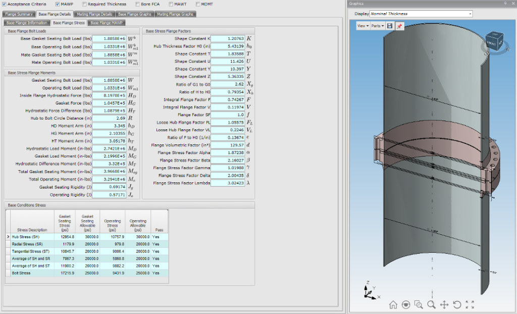
Figure 1 shows a summary of calculated flange stresses from a typical ASME VIII-1 Appendix 2 evaluation using the FLANGE module of E2G’s PlantManager™ software.
ASME VIII-1 also recognizes in Nonmandatory Appendix S that in practice, the bolt loads applied during joint assembly may well exceed the bolt allowable stress values that are used in the Appendix 2 flange design calculations. Appendix S requires that these higher bolt loads be evaluated to ensure a safe flange design but does not prescribe a specific methodology for conducting such an evaluation.
Historically, pressure vessel and heat exchanger girth flanges have often been designed to meet the requirements of ASME VIII-1 while using as little material as possible, with little regard to how that design philosophy impacts the performance of the equipment over the years of operation that follow the initial design and fabrication.
Assembly Optimization Considering Flange Leakage
ASME PCC-1, the post-construction code document for “Pressure Boundary Bolted Flange Joint Assembly,” provides an outline in Nonmandatory Appendix O for determining an appropriate assembly bolt stress using a joint component approach. This approach is based on considering minimum and maximum permissible stresses for the flanges, gaskets, and bolts such that the potential for leakage is minimized without any of the three joint components incurring damage. While some specific recommendations and component limits are provided in the document, much of the methodology for performing the calculations is left to the user.
Elastic-plastic finite element analysis (FEA) was used to develop some of the limiting stress values provided in ASME PCC-1 Appendix O, and in some cases FEA is suggested as the appropriate methodology for establishing limits for geometries that fall outside of those provided in the Appendix O tables. In fact, FEA is a reliable methodology for evaluating any bolted flanged joint for which the geometry, material behavior, and loading cycle can be well defined, but it tends to be much more time-consuming and costly than using closed-form solutions, especially if a software application can be provided for performing those calculations. E2G’s IntelliJoint software provides a tool to evaluate and optimize bolted flanged joints using closed-form calculations per the component-based approach presented in ASME PCC-1 Appendix O, provided that the flange geometry lends itself to reasonable approximation as a standard flange design, like a weld neck flange. Such an approximation can be judiciously applied to a surprising variety of flange geometries.
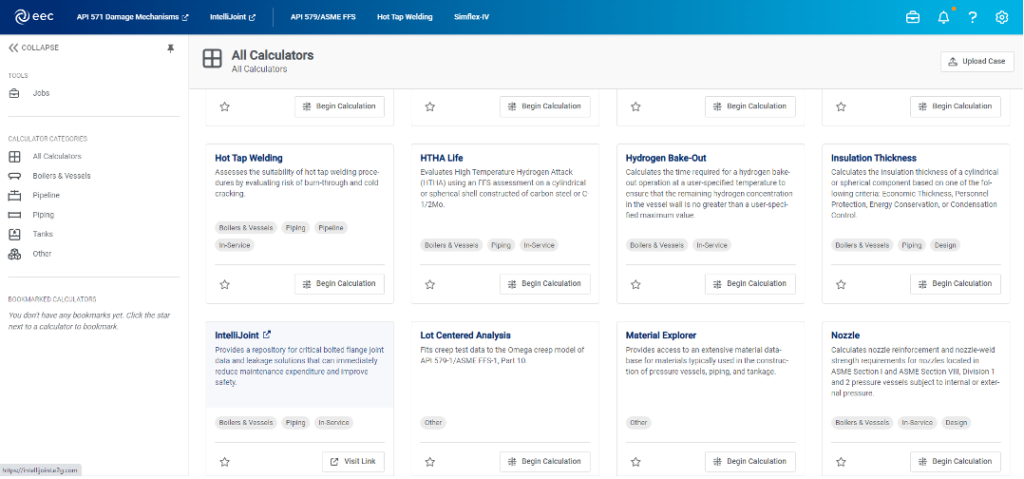
IntelliJoint is a web-based tool accessed via the Equity Engineering Cloud (eec), as shown in Figure 2.
The approach employed by IntelliJoint involves comparing the gasket stress that can be reliably developed via application of bolt loads during assembly with the minimum gasket stresses required to initially seat the gasket and maintain a seal in operation. Factors that act to reduce the applied gasket load from assembly through arrival at a steady-state operating condition are accounted for, as are maximum permissible stresses for the flanges, gaskets, and bolts.
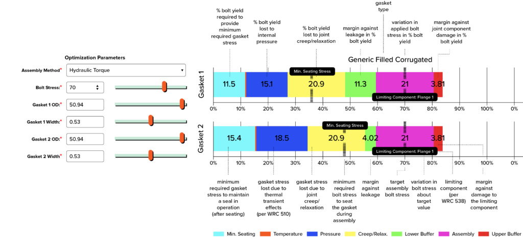
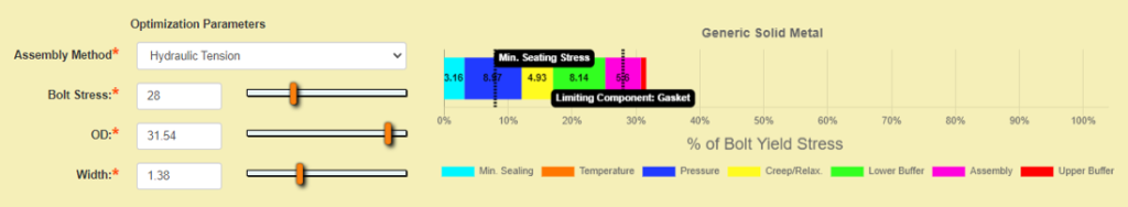
A summary of the factors considered in an IntelliJoint evaluation is shown in Figure 3, which also provides a representation of how the results are shown graphically by the software.
Minimum required and maximum permissible gasket stresses are based on established research for a number of generic gasket types, as well as values published or provided by numerous manufacturers for their specific gaskets. Maximum permissible flange stresses are calculated per WRC Bulletin 538, which used elastic-plastic FEA to establish appropriate limits for closed-form flange stress calculations based on those of ASME VIII-1 Appendix 2 but extended to additional locations. A range of assembly bolt loads is considered in the assessment based on the variability inherent in the assembly method chosen, and losses of gasket load due to joint relaxation, internal pressure, and thermal transient effects are accounted for. Currently, changes in bolt loads due to thermal transient effects are calculated via the methodology presented in WRC Bulletin 510, but the software is currently being updated to incorporate a robust thermal solver developed by E2G for use in hot tap evaluations to further improve the accuracy of the assessment.
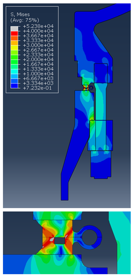
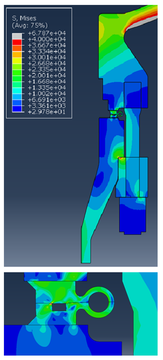
There will always be some geometries or load application cycles that will require FEA to obtain a sufficiently accurate solution, but judicious use of approximations can make it possible to obtain useful results from IntelliJoint for geometries that differ significantly from those of weld neck flanges. An example of this can be seen in a comparison of FEA and IntelliJoint results for the flanged joint in Figure 4, which shows the von Mises equivalent stress distribution in the bottom flanged joint of a reactor vessel during assembly, with only bolt loads applied. This joint employs a metallic weld ring gasket with a lip seal at the outer edge of a hollow ring. In theory, this is a seal-welded design, and no gasket seating bolt load would be required by the code. However, the seal welds at the outer edges of this and many similar lip-seal gasket designs are very small, are difficult to make due to limited access, and can be extremely intolerant of radial shear between the two halves of the gasket at the seal weld location. In this particular case, the joint was prone to frequent leakage due to cracking of the seal welds. The approach employed in evaluating this joint was to treat the weld ring gasket as a solid metallic gasket and attempt to produce sufficient contact stress to seal against the flat gasket faces, relegating the exterior seal weld to secondary seal status.
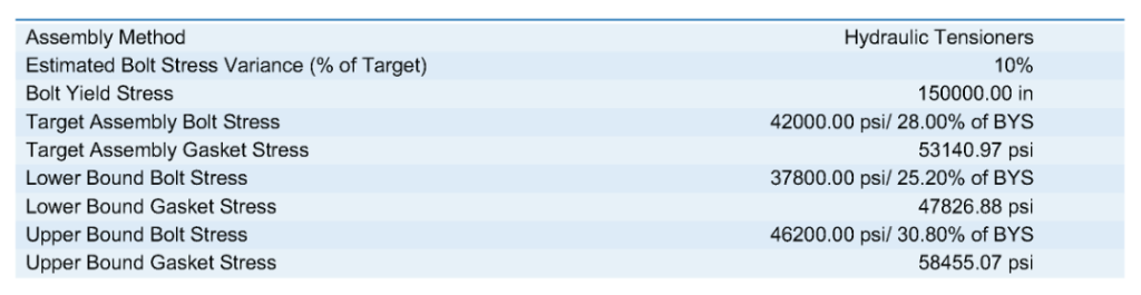
Clearly, the geometry shown differs drastically from a weld neck flange. However, approximating the geometry as a weld neck flange in IntelliJoint resulted in the optimized assembly parameters shown in Figure 5, with a target assembly bolt stress of 42 ksi for the high-strength bolting used in this application. The corresponding target assembly gasket stress calculated by IntelliJoint is a little over 53 ksi, as shown in Figure 6, while the stress contour plot shown in Figure 4 shows gasket stresses reaching just over 52 ksi in the FEA model. The gasket is identified in the IntelliJoint results as the limiting component (i.e., the component closest to reaching its maximum permissible stress).
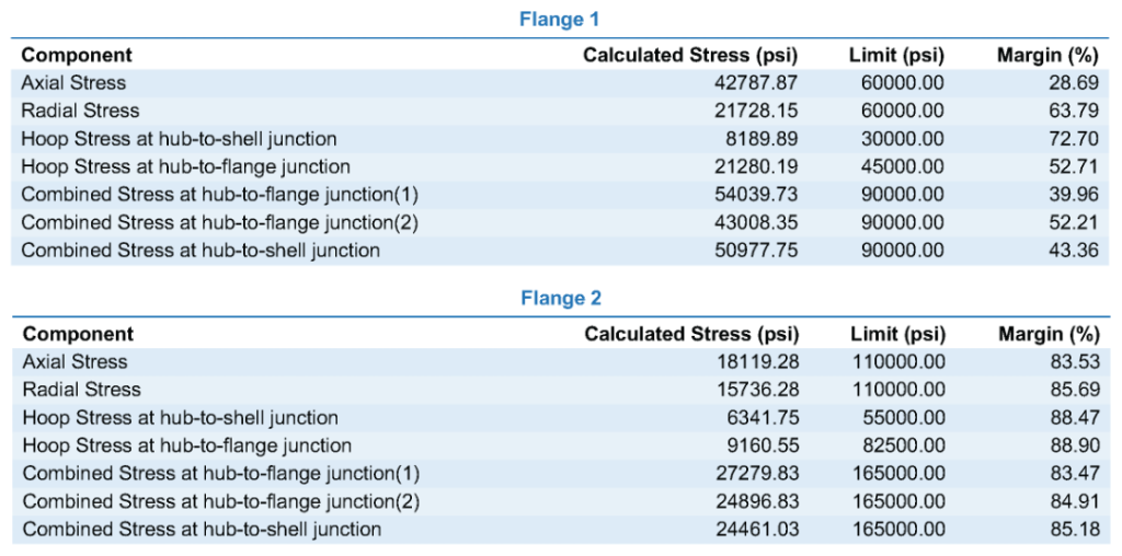
Similarly, the calculated flange stresses from IntelliJoint (shown in Figure 7) align reasonably well with those shown in the operating case FEA results presented in Figure 8, even though the as-modeled geometries differ significantly between FEA and IntelliJoint. It is important to note that had one of the flanges been identified as the limiting component, any decision regarding the necessity of further investigation via FEA would have depended in part on how closely calculated stresses in the limiting flange approached their permissible limits, since the significance of the flange geometry approximations would have to be assessed before relying on the IntelliJoint results alone in lieu of FEA.
Ultimately, evaluations such as this one show that the ASME PCC-1 component-based approach embodied in IntelliJoint can be a valuable tool in efficiently assessing and optimizing the assembly of bolted flanged joints to eliminate leakage, even for complex flange geometries. These types of evaluations have shown tremendous success in improving real-world reliability of chronically leaking joints, often completely in lieu of more complex analysis via FEA but also sometimes in conjunction with it.
For more information, submit the form below: