Introduction
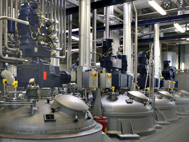
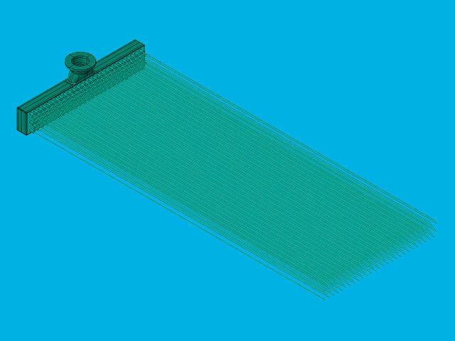
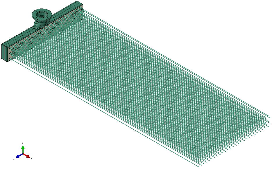
Air-cooled heat exchangers (ACHEs), or “air coolers,” are widely found throughout the process and power industries. Air coolers serve a unique function as the equipment is capable of rejecting heat directly to ambient air, thus eliminating the need for large cooling water capacities. This function is especially valuable for the midstream sector of the oil and gas industry given the typical facility designs and remote locations generally pose a challenge for cooling water access and associated maintenance needs. An air cooler will include an air-moving device, such as a fan or blower, and will be supported in a way to permit air to enter beneath the equipment. The other main component for an air cooler is the tube bundle(s) consisting of an assembly of tubes and header boxes with nozzles attached to facilitate process flow. The header box consists of a tube-sheet, top and bottom (i.e., wrapper plates), end plates, and a cover plate that may be welded or bolted on. If the cover includes plugs screwed into each hole, then the cover is called the “plug-sheet.” If designed correctly, air coolers can be a highly efficient means for heat transfer; however, the lifecycle management (LCM) of air coolers is not without challenges.
Air coolers fabricated and installed in midstream application are commonly designed with zero corrosion allowance because metal loss is not expected due to the intended service. When in-service inspection occurs at intervals from prescriptive inspection or risk-based inspection, any wall loss less than nominal thickness will require corrective action. While this may not appear to be a concern for non-corrosive service, no corrosion allowance can create unanticipated challenges requiring excessive future inspections to resolve ultrasonic thickness (UT) measurement and fabrication tolerances. Thus, it is important to understand the tools available to further evaluate air cooler remaining life to make the best use of inspection dollars and have options available to address any unforeseen internal or external damage.
Current API 579 Options for FFS
Fitness-for-service (FFS) assessments are quantitative, multi-disciplinary engineering evaluations that are performed to demonstrate the structural integrity of an in-service component containing a flaw or damage. FFS assessment is a very powerful tool in air cooler LCM because it can be leveraged to improve inspection planning and used to guide run, repair, or replacement decisions. The FFS methodology for metal loss in the air cooler involves many intricacies when compared to a standard pressure vessel component (e.g., cylinder, elliptical head). The current options for a general metal loss (GML) assessment using API 579-1/ASME FFS-1 Fitness-for-Service (API 579) of an air cooler are as follows:
- Part 4, Level 1 assessment – Calculations per the original code of construction to further refine the minimum required thickness (tmin). Code references include:
- ASME Section VIII, Division 1 (ASME VIII-1) Mandatory Appendix 13: Design of Vessels of Noncircular Cross Section, or
- ASME Section VIII, Division 2 (ASME VIII-2) Part 4.12
- Part 4, Level 3 assessment – Advanced stress analysis methods:
- Finite Element Analysis (FEA) per API 579 Annex 2D, or
- Closed-form calculations using an allowable Remaining Strength Factor (RSFa) of 0.9
Part 4, Level 1 Assessment
An air cooler’s design will dictate whether there is additional thickness available beyond the initial design corrosion allowance. The ASME Code calculations are the first step to determine whether the air cooler can withstand additional wall loss by performing tmin calculations. Note that tmin calculations for in-service air coolers can be approached in many different ways because the aforementioned tube-sheet, plug-sheet, and wrapper plates are dimensionally interdependent upon one another. For this reason, the tmin calculations can be iterative, and results will be variable depending on whether a loss is being applied to one selected plate or all plates uniformly. Thus, it is best to have a full understanding of current plate measured thicknesses and future corrosion needs prior to performing the ASME Code calculations.
A summary of common challenges that may arise during Level 1 FFS calculations is provided below alongside potential solutions that could be pursued.
Challenge #1: The dimensions for the hole pitch and the ‘dj’ variable, or the length from tube-sheet/plug-sheet centerline to center of outermost hole, are often only found on detailed fabrication drawings. For cases where design documentation is scarce, this may result in a gap in the required information to support the calculation.
Solution #1: The hole pitch and dj dimensions are easy field dimensions to determine, but with field dimensioning there is a need for planning and providing accessibility to the air cooler header boxes.
Challenge #2: Internal stay members may not be captured in the available design documentation. Drawings will typically be required to convey the stay dimensional information to credit the member in the calculations.
Solution #2: Whether a stay plate was utilized during the design and fabrication will be apparent based on initial calculation maximum allowable pressure (MAWP) results being significantly below the design pressure. The solution may require “file diving” or reaching out to the manufacturer for stay plate design information because this information is often not on the ASME Data Report. Alternatively, intrusive or nonintrusive inspection could be used to identify a stay member and support crediting one in calculations through a reasonable yet conservative placement.
Challenge #3: There is no codified procedure available to check the adequacy of the nozzle opening reinforcement for nozzle openings sizes that are not exempt from reinforcement requirements. Metal loss in an air cooler nozzle or wrapper plates adjacent to the nozzle may require calculations for the tmin of the nozzle reinforcement zone.
Solution #3: Leveraging ASME VIII-1 paragraph U-2(g), E2G has developed an engineering approach to calculate the tmin in the nozzle reinforcement zone for a nozzle in an air cooler wrapper plate. This approach requires the total available reinforcement area to meet or exceed the required area for both the longitudinal and transverse reinforcement planes. The available area is credited by excess component thickness within a defined reinforcement zone. The required area is further determined based on the opening size and the plate required thickness at the nozzle intersection for the plane being evaluated.
Part 4, Level 3 Assessment
Part 4, Level 3 FFS assessment can be performed by leveraging the closed-form calculations per the ASME Code and the RSFa of 0.9 per API 579. This option can be advantageous given its simplicity but does have inherent limitations: restricted to uniform thinning, no supplemental loadings, no cyclic conditions, no elevated temperatures, etc. This assessment approach is particularly beneficial in resolving issues stemming from air cooler designs with zero corrosion allowance.
If the closed-form solutions do not achieve the desired results, a Part 4, Level 3 FFS using FEA would be the next step for analysis. Additionally, metal loss and/or significant external loads on a non-standard nozzle design such as a swage nozzle would require performing FEA to demonstrate FFS.
Case Study #1: Level 3 Closed-form FFS
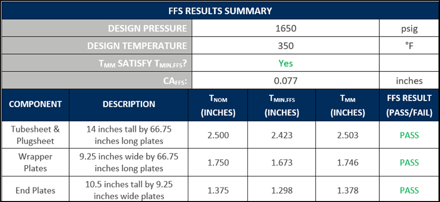
An air cooler was initially designed for 1650 psig at 350°F (176°C) with zero corrosion allowance. During routine inspection, minimum measured thickness (tmm) was found to be less than nominal thickness for the wrapper plates by 0.004 inches. E2G initially performed Level 1 Code calculations that determined a maximum future corrosion allowance (FCA) of 0.003 inches (0.076 mm) at design conditions. The tmm for the wrapper plate is less than the Level 1 Code tmin calculations, which indicates additional analysis is required. E2G then performed Level 3 closed-form calculations using an RSFa of 0.9. The Level 3 results show a maximum FCA of 0.077 inches (1.95 mm) and, therefore, demonstrate the air cooler is fit for service with FCA beyond tmm.
Case Study #2: Level 3 FEA
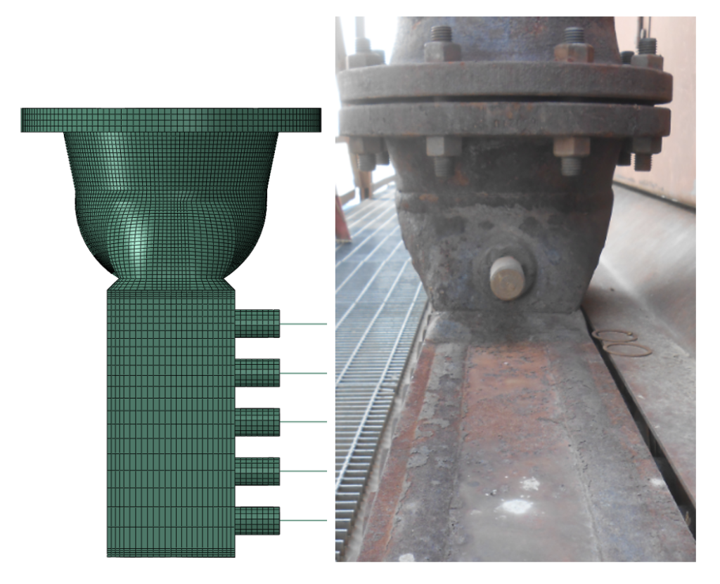
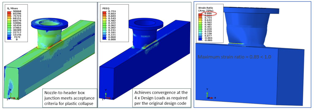
A piping analysis performed by E2G using the piping flexibility software SIMFLEX-IV was performed for a fractionator overhead line to multiple air coolers. The analysis indicated that the piping reaction loads exceed the API Standard 661, Petroleum, Petrochemical, and Natural Gas Industries – Air-cooled Heat Exchangers (API 661) allowable loads at the air cooler nozzles by a factor of 9.6 times. In addition to excessive external piping loads, the nozzle was found to have measured thicknesses less than nominal thickness within the swaged region. E2G performed a detailed FEA of the air cooler nozzles to qualify the excessive piping loads and thinned nozzle region. It should be noted that these excessive piping loads have not caused cracking, leakage, or excessive deformation of the air cooler nozzle or flange. Results of the elastic-plastic FEA of the air cooler nozzles with applied pressure and piping reaction loads indicate that the nozzle-to-header box junction meets the design margins of the original code of construction. In general, the API 661 allowable loads are intended to be conservative. The API 661 loads are based on nominal pipe size, so they are increasingly conservative for heavier-wall nozzle designs found, which was the case for this air cooler.
Future FFS Development
At E2G | The Equity Engineering Group, Inc., our consulting services, corporate standards, and industry-leading software deliver practical solutions that solve your asset challenges and meet your operational needs. E2G is dedicated to advancing FFS technology in API 579 with new focus on FFS methods unique to specialized equipment such as air coolers. As such, a method analogous to the closed-form Level 3 approach discussed herein is currently being developed as a formal Level 2 method at the committee level. These developments and others aimed at further defining Level 1 and Level 2 FFS methods provide the industry the tools needed to effectively manage fixed equipment; meanwhile, our experts at E2G are standing by to support you with your air cooler consulting needs no matter the complexity.