At a Glance:
This article highlights crucial electrical considerations for process plants, emphasizing power quality and voltage stability to prevent unplanned downtime and protect electrical infrastructure components like motors from voltage sags and surges. It also covers essential topics such as motor control centers (MCCs), proper grounding and bonding, hazardous area classification (HAC) for electrical safety, and arc flash mitigation, recommending risk-based inspection (RBI) and Internet of Things (IoT) for predictive maintenance and operational efficiency.
As industry professionals, it’s essential to stay informed about the key electrical considerations that can impact your projects. Electrical systems form the operational backbone of process plants, yet their complexities are often overlooked until failures disrupt production or compromise safety. Drawing on industry best practices, this article outlines critical electrical considerations that impact every facet of plant operations—from motor reliability to hazardous environment safety. Yes, your electrical system is operating behind the scenes, but the reliability and robustness of electrical systems are crucial. Every industrial facility should focus resources on monitoring proper power quality and careful consideration of other key electrical infrastructure components.
Power Reliability & Voltage Stability: Your Motors Are at Risk
Unstable power directly threatens process continuity. Voltage sags or surges (more than the +/- 10% of an equipment’s rated voltage) can trip critical equipment like pumps and compressors, causing cascading shutdowns. For example, a facility experiencing voltage instability can see repeated compressor or critical motor failures, leading to unplanned downtime. When unplanned downtime can cost in the hundreds of thousands of dollars per hour, ensuring a reliable supply of power at your facility is crucial.
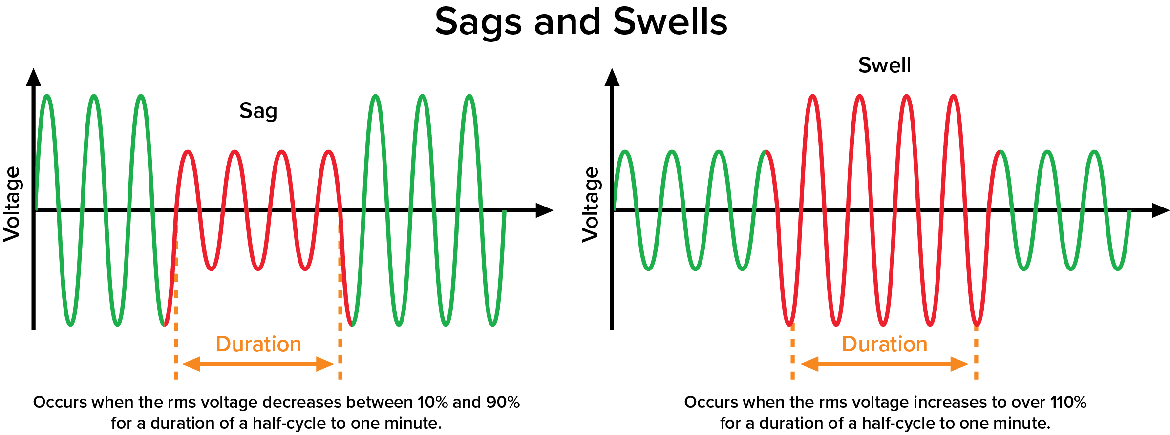
Frequent undervoltage, or voltage sag, can result in a degradation of equipment performance and reliability. When a piece of electrical equipment is supplied with voltage under the lower 10% limit, it means the equipment will draw extra current to meet the power requirements. Starting large motors or equipment—drawing a high inrush current—can cause a momentary voltage drop in the system. Other causes of a voltage sag include a short circuit in the power distribution network, lightning strikes, or utility grid issues.
Overvoltage, or a voltage surge, can occur during a power surge, lightning strike, or electrical fault. Excessive voltage weakens conductor insulation. This includes your power conductors and motor windings, compromising the dielectric properties of the insulation and causing premature insulation breakdown. Overvoltage also increases heat generation in the motor. As voltage increases in a motor, so does the current flowing through the windings. The increased current generates more heat, which raises the motor’s operating temperature even more. The elevated temperature can accelerate insulation aging, reducing insulation resistance and ultimately leading to insulation failure in the motor. Any sustained overvoltage situation can cause protective devices, such as relays and contactors, to also fail prematurely. The heat doesn’t damage only electrical equipment; the heat will induce mechanical stress on bearings, leading to increased friction and accelerated wear.
Undervoltage and overvoltage cause your motors and compressors to operate outside their design parameters and can cause a multitude of problems:
- Decreased motor efficiency – Higher current draw results in higher energy losses and a reduction in overall efficiency. The motor consumes more electrical energy while delivering the same mechanical output, leading to inefficiencies and increased operating costs.
- Abnormal motor operation – The motor may experience fluctuations in speed, torque, or unexpected and unplanned shutdowns.
- Vibration and noise issues – The imbalance caused by irregularities in motor operation can lead to excessive vibration, which not only affects the motor’s performance but can also negatively impact the overall machinery integrated with the motor.
- Disruption or destruction of sensitive electronic equipment.
Modern technology offers several solutions to mitigate the effects of undervoltage and overvoltage. Both issues pose unique challenges that require specific solutions to prevent equipment damage, operational downtime, and safety risks. It’s important to engage your facility’s electrical engineers in the diagnostic process so the most effective corrective action is taken. Understanding the differences between the symptoms of undervoltage and overvoltage is crucial for designing a more robust power system.
If your facility uses a backup generator with an uninterruptible power supply (UPS), the UPS can be sized to provide immediate backup power to maintain voltage levels during a voltage sag situation. Other energy storage systems can also be utilized depending on your specific installation. A soft start or variable frequency drive (VFD) on large motors can reduce the high inrush current situation. Lesser used solutions include dynamic voltage restorers (DVRs) and automatic voltage regulators (AVRs).
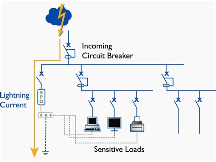
Overvoltage or voltage surges are a more commonly known phenomenon. Surge protective devices installed at service entry points or within distribution panels will divert excess voltage safely to ground. To protect sensitive electronic devices, a transient voltage surge suppressor will limit transient overvoltage by clamping it to safe levels. A lightning protection system is crucial, especially for outdoor installations, to ground lighting strikes before they can enter the power distribution system. Critical industrial applications would benefit from isolation transformers installed to separate sensitive equipment from power fluctuations. Most industrial facilities have some sort of voltage monitoring system that continuously tracks voltage levels to quickly detect and correct surges. Your facility’s power coordination study should be regularly re-evaluated and updated to ensure protective relay settings are effectively able to isolate faults without causing grid-wide disruption.
As technology advances, more IIot (Industrial Internet of Things) devices allow real-time monitoring of voltage sags and surges, enabling predictive maintenance and quick troubleshooting. AI-based predictive analysis uses machine learning algorithms to predict and mitigate voltage disturbances more rapidly, resulting in minimized downtime and improved power quality. A hybrid power quality solution that combines UPS, DVR, and surge protection in a single compact system reduces the overall infrastructure cost and increases reliability.
Motor Control & Protection
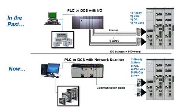
Motors drive around 70% of industrial processes, making their control systems vital. A motor control center (MCC) centralizes management while optimizing protection. Significant improvements have been made to the design of the modern MCC from its start as an electromechanical design including a contactor, thermal overload, and short-circuit protection with hard-wired lights and a local/remote selector switch.
MCCs manufactured now include microprocessor-based controllers that provide detailed event diagnostic reporting that includes a sequence of events, oscillography, motor start and stop reports, and load profiling. Diagnostics are transmitted via communication protocols specified by your facility and are typically via Ethernet or Serial ports and use IEC 61850 Generic Object-Oriented Substation Event (GOOSE) or Manufacturing Message Specification (MMS) protocols.
Grounding & Bonding
Misunderstanding grounding and bonding invites catastrophic risks. Proper grounding not only ensures the safe dissipation of static discharge in flammable environments but also prevents hazardous situations from arising. Ignoring grounding in hazardous areas such as refineries can have severe consequences. Proper grounding is analogous to the foundation of a building, providing stability and safety for the entire facility.
At a high level, below are the differences between grounding and bonding:
- Grounding directs fault currents safely to earth. Ground rods and grids are the primary components.
- Bonding equalizes electrical potentials to prevent static sparks. Bonding joins metallic equipment and structures to eliminate voltage differences.
While a seemingly simple concept, the proper implementation of grounding can be confusing. If done incorrectly, the installation cost could exceed what’s reasonable while not providing the proper or expected protection.
Hazardous Area Classification
Hazardous area classification (HAC) is a foundational aspect of electrical safety in process plants, ensuring both personnel protection and equipment reliability. The process involves systematically identifying and categorizing locations where explosive or flammable atmospheres may exist, guiding the selection and installation of suitable electrical equipment.
In the United States, the API 500 standard is predominantly used, which employs the Class/Division/Group system. This system, as outlined by the American Petroleum Institute, is aligned with the National Electrical Code (NEC). Alternatively, API 505 introduces the Zone system, which is more common internationally. This method classifies areas as Zone 0, Zone 1, or Zone 2 based on the frequency and duration of the presence of an explosive atmosphere. However, in the U.S., the Class/Division/Group system remains the standard for most process facilities.
Practical Steps in Hazardous Area Classification
A thorough HAC process involves several critical steps to ensure accuracy and safety:
- Hazard Identification: Systematically identify all sources of flammable gases, vapors, or dusts, including process points, leaks, vents, and maintenance activities.
- Data Collection: Gather detailed information on the properties of hazardous substances, such as ignition temperature, flash point, and release scenarios.
- Risk Assessment: Evaluate the likelihood and potential impact of hazardous atmospheres, considering process conditions, volume, pressure, and ventilation.
- Area Delineation: Assign Class, Division, and Group to each area based on the type and probability of hazard. Use plant layout drawings to determine the extent and boundaries of hazardous zones.
- Equipment Selection: Specify electrical and mechanical equipment certified for use in each classified area, ensuring compliance with relevant standards and reducing ignition risk.
Engineering and Operational Considerations
- Avoid Blanket Classification: Each room or area should be individually assessed rather than applying a broad classification to the entire facility, which can lead to unnecessary costs and increased risk.
- Use of Boundaries: Clearly defined physical boundaries (walls, floors) simplify design, installation, and ongoing maintenance.
- Control Measures: Implement additional safeguards such as grounding, explosion-proof equipment, adequate ventilation, and strict control over ignition sources (e.g., hot work permits, vehicle restrictions).
- Documentation and Review: Prepare comprehensive documentation of the classification, including diagrams, boundaries, and rationale, for review and approval by the project team.
By following these structured practices and adhering to recognized standards like API 500, process plants can effectively mitigate the risks associated with hazardous areas, ensuring both regulatory compliance and operational safety.
Arc Flash & Electrical Safety
Arc flashes release energy equivalent to an explosion. This dangerous energy release in electrical equipment causes severe burns, injuries, and equipment damage. It’s triggered by faults like short circuits, loose connections, or insulation failure.
Effective arc flash mitigation follows a control hierarchy: eliminate hazards first, use engineering controls, then administrative controls, and finally personal protective equipment (PPE) as a last resort. See Equity Industry Insights article “NFPA 70E: Creating an Electrically Safe Work Condition” for more information.
Diagnostic Techniques
A risk-based inspection (RBI) of your electrical equipment can help to identify overvoltage-related damage in electric motors. The following techniques can aid in detecting and mitigating such issues:
- Visual inspection – burnt insulation, discoloration, or melted components.
- Monitoring motor performance – continuous monitoring of key motor performance parameters, such as bearing temperature, motor temperature, current, voltage, and vibration, can help to provide an early detection of any issue.
Actionable Takeaways
- Engage electrical engineers early in design changes to avoid retrofits.
- Updated power coordination study – Implement graded relay settings to isolate faults without grid-wide disruption.
- Perform load analysis to calculate operational peak loads, ensuring transformers and cables are correctly sized. Underestimating loads risks overloads and fires.
- Implement RBI programs for transformers, MCCs, and protection relays.
- Regular inspection and maintenance reduce unplanned downtime and extend equipment lifespan.
- Scheduling an inspection of all electrical equipment helps prioritize and identify the backbone of electrical infrastructure at risk of causing unplanned outages, thereby forming a comprehensive plan for replacements, upgrades, and risk mitigation.
- Verify HAC has been completed properly.
- Train operations teams on arc flash boundaries and PPE use.
- Embracing innovations like smart sensors and IoT can optimize energy consumption and improve monitoring capabilities within your facility.
Electrical infrastructure strength in process plants isn’t theoretical—it’s foundational. By prioritizing these practical considerations, plants achieve safer, more reliable, and more efficient operations. For tailored electrical system assessments or RBI planning, contact the author for a consultation leveraging 15+ years of industry-specific expertise.
Please contact the author with any questions by submitting the form below: