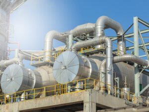
One very common problem in the chemical industry is two-phase flow in pipes. Process equipment such as chemical reactors, storage tanks, various types of heat exchangers, and contact equipment involve significant gas-liquid flow. Proper design of the lines in these types of equipment carrying two-phase flow is key to preventing costly overdesign or malfunction.
The most significant phenomenon associated with two-phase flow is that all transport properties – such as heat, mass, and momentum transfer – increase and become greater than those of a comparable single-phase system.
The factors that make two-phase flow problematic are:
- Two-phase flow cannot be characterized simply as laminar, turbulent, or a combination of both, but rather depends on the relative amounts and distribution of the phases. Even when it is possible to determine whether the flow is laminar or turbulent, fundamental relationships are difficult to apply/ascribe to the free surfaces of the phases.
- Due to the difference in the densities of the phases, the flow pattern in horizontal or inclined pipes is not symmetrical with respect to the flow axes.
- In cases involving a large amount of interfacial surface area, the energy associated with the creation of this surface must be considered in the overall energy equation.
- Because it must be accounted for in the fundamental equations, the presence of an interface itself exacerbates the problem’s complexity.
- In the general case, the phases may not be in equilibrium with respect to temperature or component concentrations, meaning that mass and heat transfer relationships must be considered. Fortunately, in two-phase mixtures, mass and heat transfer rates are high due to the large interfacial area, good mixing, and often the presence of turbulence. As a result, equilibrium can typically be assumed without significant loss of accuracy.
- In most cases, the separate phases move at different average velocities, and the mass concentrations are the same as those at which they are introduced into and removed from the system.
The variation in the supplied concentrations refers to the “holdup.” Holdup is defined as the fraction of a pipe’s volume or cross-sectional area that is occupied by a specific phase (liquid or gas) at any given instant. Unlike single-phase flow, where the fluid fills the entire pipe, multiphase flow involves two or more fluids (like oil and gas) traveling together. Holdup describes the in-situ or actual amount of each fluid currently inside the pipe.
Holdup matters in process simulation for several reasons:
- Pressure drop: to calculate the pressure required to move the fluid, bulk fluid density is critical. Since liquid is much heavier than gas, a high liquid holdup significantly increases the hydrostatic weight of the fluid column.
- Flow regime identification: the transition between patterns (like bubbly, slug, or annular flow) depends heavily on how much liquid is “held up” in the line.
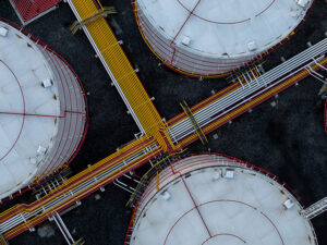
- Equipment sizing: if a pipeline has high holdup, a sudden change in flow rate can sweep all that accumulated liquid out at once. Downstream equipment like slug catchers must be large enough to handle this sudden volume.
- Inventory management: in transfer and distribution pipelines, knowing the holdup allows the engineer to estimate the total volume of fluid currently trapped in the system.
Holdup is a variable/parameter that, because it is not a constant, is better determined by developing a dynamic hydraulic analysis; it changes based on:
- Pipe inclination: liquid holdup is highest in upward-sloping pipes (where gravity fights the liquid) and lowest in downward-sloping pipes.
- Fluid process velocities: higher gas velocity generally reduces liquid holdup by pushing the liquid out faster.
- Fluid properties: high-viscosity liquids (like heavy oil) have much higher holdup because they move more slowly.
Derived from the above factors, it is necessary to calculate the three pseudo-properties representing the properties of the two-phase flow: density, viscosity, and velocity.
What are the most important aspects to consider in a two-phase hydraulic analysis?
- Identify the thermodynamic behavior of the fluid. Verify whether the liquid/vapor ratio is constant or variable.
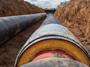
- Identify the routing of the process lines. Are they horizontal, vertically downward, or upward?
- Diagnose/evaluate the two-phase flow regime.
- Verify the availability of the maximum pressure drop.
- Calculate the pressure drop and define/confirm the line diameter.
- Confirm the absence of problematic flow regimes (e.g., dispersed flow at the inlet of separators and/or columns, slug/plug flow in condensate transfer lines).
Where is two-phase flow typically found?

What are the most common problems resulting from two-phase flow?
- High pressure drop
- Undesirable flow patterns under certain conditions
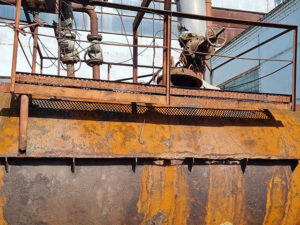
- Erosion and corrosion due to high process velocities
The most undesirable two-phase flow regime in the industry is slug flow. Slug flow develops when waves of liquid are picked up periodically in the form of frothy slugs that move at velocity greater than that of the average liquid. Typically, this phenomenon may occur in a pocketed line between an overhead condenser at grade and an elevated reflux drum. At low velocities, liquid collects at the low point and can periodically become a slug in the line. With sufficiently high velocity, the liquid phase can be carried through without developing slug flow.
This is an intermittent multiphase flow regime where gas and liquid move through a pipe in alternating, distinct packets. It is one of the most complex and problematic flow patterns in engineering because of its unsteady nature and the high-momentum forces it exerts upon piping systems.
To understand this problematic flow regime, it important to define the “slug unit,” which is composed of three primary regions:
- Liquid slug (slug body): a dense, high-speed plug of liquid that typically fills the entire cross-section of the pipe. This slug body often contains small, entrained gas bubbles.
- Gas pocket: a large, bullet-shaped gas bubble (in vertical pipes) or an elongated gas pocket (in horizontal pipes).
- Liquid film: a thin layer of liquid that flows along the pipe wall underneath or around the gas pocket. As the gas pocket passes, liquid is shed into the film at the back and picked up by the next incoming liquid slug at the front.
Furthermore, the slug period is defined as the time required for one full slug unit, consisting of a liquid slug and its following gas pocket, to pass a fixed point in a pipeline. The slug period is the mathematical reciprocal of the slug frequency.
Determining the slug period is critical for designing separators and slug catchers, as it dictates the volume and timing of liquid surges arriving at processing facilities. The critical parameters of slug flow to consider when a dynamic hydraulic analysis is under development are shown in the following table.
| Parameter | Description | Typical Impact |
| Slug Frequency | The number of liquid slugs passing a fixed point per unit of time [Hz]. | Determines the vibration frequency of the piping system. |
| Slug Length | The physical length of the liquid plug. In stable flow, it is often 20 – 40 times the pipe diameter. | Dictates the volume of liquid that will hit downstream equipment at once. |
| Translational Velocity | The speed at which the slug unit moves. This is usually 1.2 – 2.0 times the bulk fluid process velocity. | Used to calculate the impact force at elbows and tees. |
| Liquid Holdup | The fraction of the pipe volume occupied by liquid within the slug body. | Essential for calculating the total mass and momentum of the slug. |
Not all slug flows are created equal – each is generally categorized based on how it is formed: hydrodynamic slugging or terrain-induced slugging. Characteristics of each form are defined in the following table.
| Aspect | Hydrodynamic Slug | Terrain-Induced Slug |
| Primary Cause | Flow instability and wave growth | Pipe elevation changes and liquid accumulation |
| Typical Location | Horizontal pipes | Pipelines and wells with low points/risers |
| Formation Mechanism | Waves grow until they touch the pipe top | Liquid blocks gas, gas builds pressure, breakthrough |
| Slug Length/Period | Short slugs, frequent | Long slugs, long periods |
| Severity | Usually moderate | Often severe |
| Impact Downstream | Fluctuating flow and pressure | Large liquid surges, pressure spikes, flooding risk |
Slug flow causes pressure fluctuations in piping, which can upset process conditions and cause inconsistent instrument sensing. Because it is inherently unstable, it presents several risks:
- Mechanical stress & vibration: when a high-density liquid slug hits a 90-degree elbow at high process velocity, it creates a massive momentum change. This causes enough vibration in the process piping and can lead to fatigue failure of pipe supports.
- Pressure surges: the alternating phases cause rapid fluctuations in line pressure, which can trip sensors or cause chatter in control valves.
- Separator flooding: downstream separators must be sized (using a slug catcher) to handle the sudden surge of liquid volume; otherwise, liquid might carry over into the gas compressors.
- Accelerated corrosion: the turbulence in the mixing zone at the front of a slug unit can strip away protective scales on the pipe wall, leading to flow-induced corrosion.
Slug flow can be avoided in process piping by:
- Reducing line sizes to the minimum permitted by available pressure differentials.
- Designing for parallel pipe runs that will increase flow capacity without increasing overall friction loss.
- Using valved auxiliary pipe runs to regulate alternative flow rates and thus avoid slug flows.
- Using a low-point effluent drain or bypass.
- Arranging the pipe configurations to protect against slug flow (e.g., in a pocketed line where liquid can collect, slug flow might develop).
Slug flow will not occur in a gravity-flow line. A hard tee connection (i.e., flow through the branch) at a low point can provide sufficient turbulence for more effective liquid carryover.
A diameter adjustment, coupled with gas injections, can also alter a slug flow pattern to bubble or dispersed flow. Gas addition (used solely to avoid slug flow) can be expensive.
An accurate and rigorous dynamic hydraulic analysis of two-phase vapor-liquid flow in process lines requires detailed numerical methodologies. The Tulsa University Fluid Flow equation is a mechanistic model that, unlike simple empirical correlations (e.g., Beggs and Brill correlation), includes several correlations to calculate multiple properties, is based on flow physics, and is widely considered the industry standard for multiphase flow. Depending on the route of the piping, the Xiao horizontal model and the Ansari vertical model will be combined in the Zhang model to achieve the most accurate result. These models are not a single equation, but a set of momentum and continuity balances applied to a specific flow regime. The Tulsa University Fluid Flow Project (TUFFP) contributed the Unified model, which treats all flow regimes as variations of a “slug unit.” This approach posits that every flow regime can be mathematically derived from the slug flow equations by adjusting the lengths of the liquid slug (slug body) and the liquid film. Thus, the fluid model is recommended when a dynamic hydraulic analysis is required.
Effective design of two-phase systems hinges on a rigorous assessment of liquid holdup and its resulting flow regimes. Slug flow remains the most formidable challenge, threatening mechanical integrity and process stability through high-momentum surges and unsteady pressure fluctuations. By applying mechanistic models like the Unified model, engineers can accurately predict these dynamics and implement strategic piping configurations to mitigate risk.
If you have a question for the author or would like follow-up, please fill in the form below:
References
- A.A. Durand, Two-Phase Flow, IMIQ Magazine, 1999.
- Robert Kern, Piping Design for Two-Phase Flow, Chemical Engineering Magazine, 1975.
- Symmetry Process Simulation Platform User’s Manual, 2025.
- Ernest E. Ludwig, Applied Process Design for Chemical and Petrochemical Plants, Elsevier, 1995.
- Tulsa University Fluid Flow Project, Eissa M. Al-Safran and James P. Brill, Applied Multiphase Flow in Pipes and Flow Assurance, Society of Petroleum Engineers, ISBN 978-1-613399-492-4.