This article discusses the challenges and possible solutions for measuring the level of petroleum and petroleum products in mature atmospheric storage tanks. “Mature” in this context refers to tanks that were constructed in the 1950s–1970s timeframe. They may have been modified over the years, but the original construction was based on standards and norms at the time they were built. As standards have evolved and the desire has increased for remote monitoring and less human intervention, reliable solutions for monitoring of levels and associated automation have become an increasing challenge.
History of Tank Level Measurement
The earliest form of tank gauging was manually done with a form of weight on the end of a graduated tape that is lowered into the tank until it reaches either the liquid surface or a datum plate near the bottom of the tank. This method is still used today, even for custody transfer. The API Manual of Petroleum Measurement Standards (MPMS) Chapter 3.1A provides guidance on how to perform a manual measurement. Since it is a manual action, errors can result from lack of consistency in repeating the method in which it is done. In addition, this exposes the operator to potentially dangerous vapors in the tank.
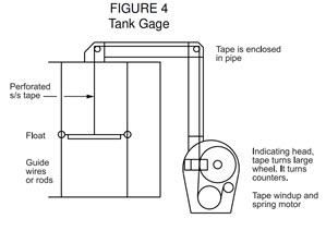
The next generation of level measurement was a float attached to a tape which ran to an indicator at grade. As the float moved up and down in the tank, the mechanism inside the indicator displayed the level according to how much tape was pulled from it or rewound inside of it by a spring. As an enhancement, electronics were attached to the indicator at grade that converted the revolutions of the indicator to an analog signal, and the tank level could be remotely displayed by running signal cable from the indicator to the control room. The electronic signal was dependent on proper functioning of the float and tape and did not provide an independent measurement. The float and tape were subject to failures including the tape breaking, the float or tape getting stuck, the guide wires that stabilized the float inside the tank breaking, or the spring inside the indicator breaking. It did, however, limit operator exposure to the contents of the tank, although vapors could still enter the pipe that contained the tape.
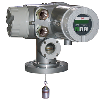
A variation on the float was a displacer attached to a thin wire which ran to a servo gauge on top of the tank. The gauge sensed the weight on the wire and adjusted a motor to keep the displacer at the liquid level while reading revolutions of the motor to determine, display, and transmit the level in the tank. The gauge required a still pipe (or stilling well) to keep the displacer from drifting inside the tank. Although this was an improvement on the float and tape gauge, this method of measurement still contained numerous mechanical parts, was subject to some of the same failures as the float gauge, and added the complication of a servo system and weight measurement. As with the float and tape, there was no independence of the local readout and electronic signal since both depended on proper functioning of the displacer, wire, and servo system. This type of measurement also limited the possibility of operator exposure to vapors in the tank.
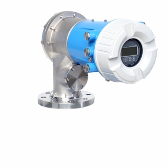
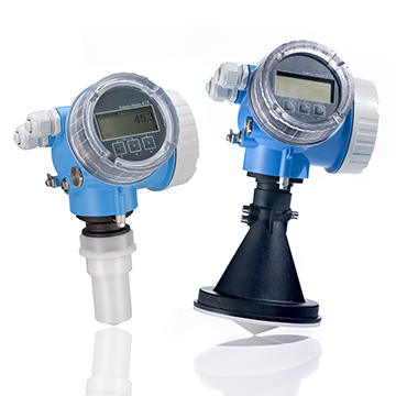
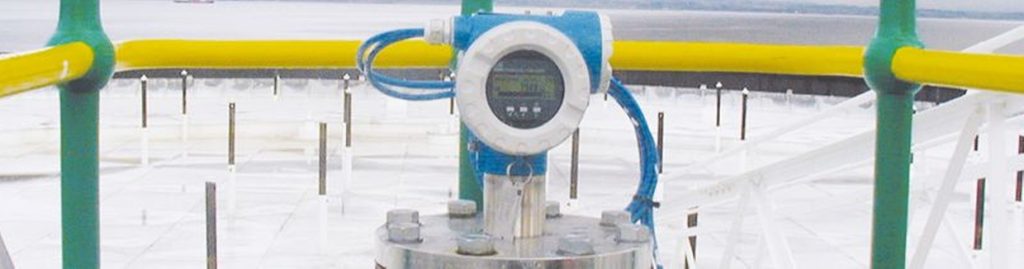
The next development was non-contacting radar gauges, and this has become the preferred technology to date. The radar gauge emits microwave energy which reflects off the surface of the liquid in the tank and returns to the gauge. The gauge measures the time from when the microware energy was emitted to when the “echo” returns, and calculates the liquid level based on the time it took to travel through the vapor space and the reflection return through the vapor space. The gauge depends on a sufficient difference in dielectric between the vapor and liquid so that the reflection is of sufficient magnitude to be consistently detected. Radar measurement has no moving parts and is, therefore, only subject to failures of the electronics, “false echoes” from interference inside the tank or still pipe, and human errors such as misapplication or faulty configuration. The measurement can be displayed locally at the tank on a digital readout and transmitted to a control room via analog or digital communication. Unless redundant radar gauges are installed, the local readout and transmitted signal lack independence. The radar gauge does eliminate operator exposure to vapors in the tank.
All the above automatic tank gauging technologies are available today: float and tape, servo, and radar. Although differential pressure, capacitance, and ultrasound have been used in various applications in the past and are still used today, they are rarely used as the primary level measurement for large petroleum and petroleum products tanks. Differential pressure is subject to changes in density, the lower connection can become plugged with sediment, and the reference line (if used) must be kept free of condensation or filled with a fill fluid. Diaphragm seals can be used in conjunction with differential pressure measurement but are normally not practical for very large storage tanks unless the transmitter is referenced to atmosphere versus the vapor in the tank. Capacitance is also normally not practical for large storage tanks. Radar has proven to be more effective than ultrasound, and the modern versions have very good built-in diagnostics and diagnostic tools.
Temperature Measurement
To strictly measure level (liquid height), it is not necessary to know the temperature of the liquid inside the tank. Level is level regardless of the temperature. For converting the level to volume, however, temperature is critical. Although temperature measurement is not technically difficult, provisions must be made so that the temperature can be measured at an appropriate location or locations in order to make a valid conversion to volume. In addition, the temperature measurement(s) must be displayed locally or transmitted to a location where a control or computer system will automatically make the conversion based on level, temperature, and the tank strapping table. Conversion to volume is essential if the tank level measurement will be used for custody transfer. API’s MPMS Chapters 7.1, 7.2, and 7.3 provide guidance on tank temperature measurement. Temperature measurement is not addressed in this article.
Challenges for Mature Atmospheric Storage Tanks
Assuming a risk or hazard analysis, a standard or regulation, change in tank service or operation, or simply the desire to improve tank operation is driving the need for different or additional instrumentation, the tank must be reviewed to determine how best to address the required change or addition. The biggest challenges for mature tanks are the connections available for level measurement, existing instrument-related infrastructure, the type of tank, and environmental regulations that may apply.
- Does the tank already have automatic level measurement?
- Does the tank have any provision for connecting level instrumentation other than the still pipe (or stilling well) used for manual level measurement?
- If the measurements are to be communicated and displayed at a remote location, what infrastructure is in place to accommodate new or additional signals?
- What type of tank is it—fixed roof (cone or dome), external floating roof, internal floating roof?
- What environmental regulations apply?
- Can a slotted or perforated still pipe be used on an external floating roof tank?
The following tables provide suggestions on how to modify or add instruments to existing tanks, even if it is a temporary solution until more permanent changes can be made. See API MPMS Chapter 3.1B for guidance on automatic tank gauging including still pipe configurations and required accuracies depending on the service. Although the primary focus of this article is continuous level measurement, point level measurement may address a requirement for alarming or automation (e.g., automated overfill prevention system). Suggestions for point level measurement, therefore, have been included in the following tables in addition to suggestions for continuous level measurement.
Click Here to Download the Level Measurement Technologies for Mature Atmospheric Storage Tanks Table
DownloadConclusion
Every tank and situation is unique. E2G can help with atmospheric storage tank risk assessments, hazard analysis, API 2350 implementation, storage tank risk-based inspection (RBI), mechanical integrity (MI) gap assessments, and cost-effective solutions for adding or modifying instrumentation on existing tanks to achieve the owner/operators safety, environmental, and business goals.