Introduction
Dissimilar metal welds (DMWs) are often specified in process plants as an alternative to bolted mechanical joints and have been successfully used in many corrosive and severe services. Common DMWs that can become problematic include joints between ferritic steel (e.g., carbon steel, 1.25Cr-1Mo) and stainless steel (e.g., 304, 2205) or Ni-base alloys (e.g., Alloy 800H, Alloy 625). Other dissimilar metal combinations such as welds between austenitic stainless steels and Ni-base alloys or welds between different grades of carbon and low-alloy ferritic steels present far fewer issues since they do not have such inherent composition or metallurgical phase mismatch. Cladding is another common form of DMW. Large structural steel pressure vessels are often clad with stainless steel to provide a corrosion-resistant layer at lower cost. While advantageous to performance and cost, there can be major weldability challenges with DMWs. This article will provide an overview of common DMW failure mechanisms, discuss challenges with weld repairing DMWs, and offer best practices to ensure successful repairs, in addition to presenting a case study of a DMW failure between Grade 91 (9Cr-1Mo-V) and 800H (20Cr-32Ni).
Failure Mechanisms with Dissimilar Metal Welds
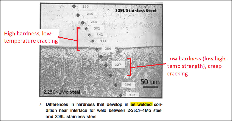
Several failure mechanisms are associated with DMWs due to the inherent differences in chemical composition, mechanical and physical properties, and corrosion resistance between the base metals. At a baseline, all DMWs are subject to dilution. Similarly, in DMWs between a ferritic base metal and austenitic weld metal (especially one with more chromium alloying), carbon migration/diffusion across the interface may occur during exposure to elevated temperatures. The resulting composition transition region between the bulk weld metal and base metal may have a distinctly different microstructure and properties than the adjacent regions. Transition zones as shown in Figure 1 may be created in DMWs such as in welds between stainless steels and low-alloy steels where martensite may form in the transition region even though it does not occur elsewhere in the weld[2]. In a hydrogen-charging environment (e.g., wet H2S), this hard zone can lead to premature cracking. Almost universally, the problems encountered are on the ferritic side of dissimilar welds joining ferritic to austenitic (stainless steel or Ni alloy) made with austenitic (stainless steel or Ni) fillers, as opposed to on the austenitic side.
The difference in thermal expansion rates between the two base metals and the weld metal can result in localized stress and strain that will exacerbate cracking mechanisms such as thermal fatigue and creep, particularly at elevated temperatures. The coefficients of thermal expansion of ferritic materials (e.g., steels) and austenitic materials (e.g., 300-series stainless steel and nickel-based alloys) can differ drastically (see Table 1)[2][3].
| TABLE 1: COEFFICIENTS OF THERMAL EXPANSION FOR COMMON MATERIALS[2][3] | |
| Material | Coefficient of Thermal Expansion (in./in./F x 10−6) to 800°F (425°C) |
| 410 SS | 6.7 |
| 9Cr-1Mo | 6.7 |
| Low Cr Steel (e.g., 1Cr-½Mo & 2¼Cr-1 Mo) | 7.53 |
| Carbon Steel | 7.97 |
| Alloy 600 | 8.0 |
| Alloy 800 | 9.2 |
| 300-series SS | 10.05 |
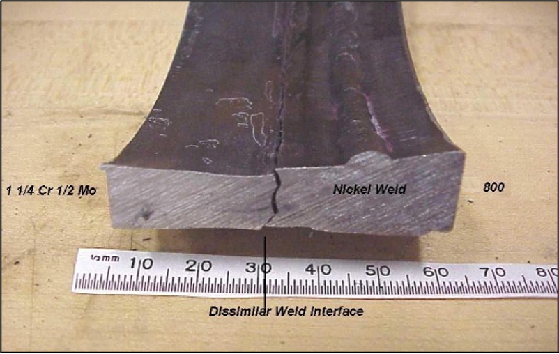
In general, differential thermal expansion cracks tend to form at the toe of the weld in the heat-affected zone (HAZ) of the ferritic material. An example of this is shown in Figure 2 with the cracking of a DMW joining 1.25Cr-0.5Mo to Alloy 800H. This failure occurred in a hydro-dealkylation (HAD) reactor effluent operating at 875°F (468.3°C) and with a hydrogen partial pressure of 280 psig. In this case, blistering and disbondment led to crack propagation at the fusion line between the 1.25Cr-0.5Mo side and the Ni-base filler buttering layer.
The corrosion resistance may also vary locally in both the deposited weld metal and the transition region due to differences in composition and microstructure. In addition to hardness variations across the fusion line as already discussed, small differences in composition and microstructure can lead to a local galvanic effect when these regions are connected in a suitable electrolyte. In this scenario, preferential accelerated corrosion may occur in any of the weld regions based on galvanic activity. Generally, the more noble material is protected by sacrificial corrosion of the more active material (anode), and the anode corrodes at a higher rate than if it were not electrically connected to the cathode.
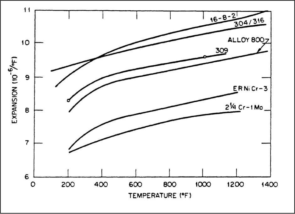
Best Practices for DMWs
To ensure a sound joint, a range of engineering and metallurgical issues must be addressed when designing a DMW. Filler metal selection for DMWs is crucial for preventing the failure mechanisms discussed above, and it is necessary to choose a filler metal composition dissimilar from the base metals to produce a heterogeneous fusion zone[1]. For example, when joining ferritic steel to austenitic stainless steel (P-No.8), the filler metal selection is dependent on the design temperature of the application. E/ER309/L is used when operating below 600°F (315.6°C), while Ni-base fillers are required for temperatures above 600°F (315.6°C)[4]. Type 309 filler has sufficient alloy content to accommodate dilution from the ferritic base material while remaining austenitic and free of detrimental phases. However, since there exists a difference in thermal expansion between ferritic steel and austenitic stainless steel (see Figure 3), Ni-base fillers are employed to transition the thermal expansion, as it lies midway between austenitic stainless steel and carbon steels. The introduction of an austenitic phase (via stainless steel or Ni-base filler) has mixed effects in hydrogen-charging environments. The solubility of hydrogen in austenite phase is much higher than in ferrite, which will generally lower hydrogen embrittlement concerns. However, high-temperature service (>800°F for carbon steel or > 950°C for Cr-Mo alloy steels) or post-weld heat treatment (PWHT) encourage carbon diffusion from the ferritic material to the fusion line, creating a hard zone that is more prone to cracking in hydrogen-charging (e.g., wet H2S) environments. At high temperatures or with PWHT, this occurs regardless of whether austenitic stainless steel or Ni filler metal is used. For this reason, PWHT of DMWs does not necessarily prevent environmental cracking if the weld is exposed to wet H2S conditions.
Another common use of a Ni-base filler metal is weld repairing cracking in high-alloy cladded material which penetrates into the base metal. As discussed in WRC Bulletin 556, coke drum shells, typically low-alloy ferritic steel (e.g., C-0.5Mo, 1.25Cr-0.5Mo) cladded with a ferritic stainless steel (e.g., 410S, 405)[6], are prone to thermal fatigue cracking and subject to numerous weld repairs. In these repairs, a Ni-base alloy is often preferred for the entire weld repair as opposed to a matching filler weld build-up and clad restoration because it is a non-hardenable material (unlike ferritic Cr-Mo filler) and is used in conjunction with controlled deposition welding (CDW) techniques to avoid PWHT. A schematic showing the repair weld in the wall of a clad coke drum wall is shown in Figure 4, as taken from WRC 556[6].

While Ni-base alloys are readily welded onto carbon steel or Cr-Mo alloy, as well as any stainless steel clad material, there still exists a slight difference in thermal expansion between the different materials, and the use of these fillers has its limitations. As reported in API TR 934-G, some owner/operators have determined through experience that high-nickel alloy repair welds in coke drums tend to crack and fail in less time than a matching Cr-Mo repair weld deposit, whether or not a CDW procedure is used[7]. As a result, it is generally recognized that repairs performed with a high-nickel alloy consumable are considered temporary and that it is necessary in the near future to replace the deposit using a matching consumable. This elevated cracking risk is thought to stem from the mismatch of thermal expansion between carbon steel / low-Cr steel and the high-nickel fillers.
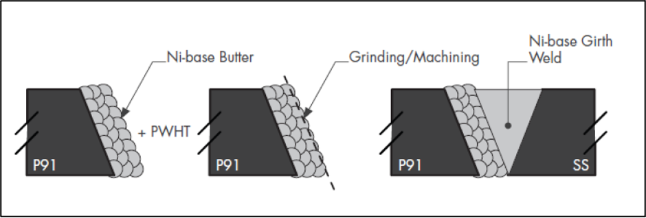
In cases of severe thermal expansion mismatch and system loads contributing to restraint or thermal stresses, especially when operating in the creep regime, a transition material and/or buttering layer may be used to accommodate thermal stresses, minimize decarburization, and improve weldability. Buttering is typically performed with a Ni-base filler metal and is intended to produce a new, as-cast microstructure under conditions of minimal restraint which can accommodate thermal contraction of the weld deposit, reducing the likelihood of cracking[8]. Buttering can also be used to alleviate PWHT requirements of the completed DMW joint where a heat treatment would be detrimental to one of the base metals. In this scenario, a buttering layer may be applied to the base metal requiring PWHT, the PWHT can be performed on the buttered base metal, and finally the dissimilar metal joint can be welded. An example of the buttering layer sequence for a DMW between Grade 91 and austenitic stainless steel is provided in Figure 5.
Case Study: Grade 91 to 304SS DMW in a Steam Superheater Header
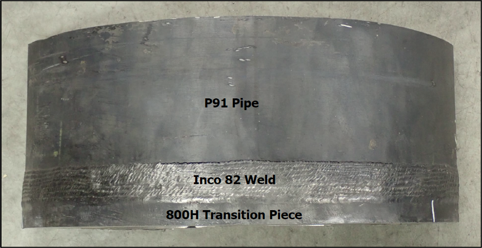
Equity Engineering was approached to provide engineering review and analysis related to cracking on the outlet piping header from a high-pressure steam superheater. The outlet manifold of the heater coil was constructed of 304H SS and the piping was constructed of P91 material. The original design was a buttered joint between the 304H and P91 with Inconel 82 filler metal. This design experienced several cracking failures at the P91 HAZ, and then section design was upgraded to include a transitional Alloy 800H pup piece welded with Inconel 82. However, this configuration experienced cracking again in the HAZ on the P91 side of the weld (see Figure 6). Equity Engineering was asked to determine the cause of repeated failure through laboratory analysis and provide repair guidance such that a successful weld could be made.
Upon investigation in a laboratory setting, cracking was found to strictly follow the fusion line in the HAZ on the P91 side of the DMW (Figure 7). The cracking morphology was consistent with DMW creep cracking in Ni-base DMWs due to cavity nucleation, growth, and linkup at an array of carbides that form in a very narrow band of the partially mixed zone (PMZ), nearly along the fusion line (Figure 8). The detrimental carbides form as a result of a narrow band of carbon-depleted ferrite during elevated temperature operation. This region is subject to significant strain concentration, which will allow creep damage in the form of cavitation to accumulate. Failures of this nature appear differently than conventional matching-weld creep HAZ damage. Conventional HAZ creep in ferritic materials tends to manifest as a wider band of damage (on the order of hundreds of microns wide) in the fine-grain HAZ or as creep cracking/low creep ductility in the coarse-grain HAZ. In contrast, the creep cracking associated with dissimilar welds is often confined to a much narrower band of perhaps only 5-10 microns or less, immediately at the fusion line/PMZ on the ferritic side of the weld. The creep damage initiates at the aforementioned detrimental carbides that form along this line, and the subsequent creep crack may display little to no additional creep fissures surrounding the main crack (distinguishing it from conventional creep cracks in HAZs, which tend to be surrounded by a field of creep-damaged material characterized by distributed voids and fissures).


To repair this location, Equity Engineering offered the following key recommendations to directionally improve the DMW and maximize the creep rupture life of the joint:
- A two-pass butter layer should be applied to the P91 weld groove to help accommodate thermal contraction stress during welding.
- PWHT should be performed after the buttering but before proceeding to the groove weld fill passes.
- A modified wide weld cap and step bevel design should be used for the repair to force subsurface cracks to propagate to the surface and impede through-wall crack propagation (see Figure 9). The step bevel with wide cap provides more resistance to creep crack growth than a standard weld bevel. A crack near the root portion of the step bevel must grow through comparatively creep-stronger austenitic (stainless steel or Ni) material before it proceeds through wall. A crack near the OD portion of the step bevel must grow through the region of ferritic base material (comparatively more crack resistant than the PMZ/HAZ) as well as the weld cap. The joint design – in theory – provides more time for inspection to detect the cracking, a greater resistance to catastrophic failure, and promotion of leak-before-break behavior[9].
- An Alloy 600/601 transition piece should be used instead of the current Alloy 800H material to better transition the coefficient of thermal expansion between 304SS and P91.

Summary and Conclusions
DMWs undoubtedly have use in industry due to their advantages in terms of process application, cost, and performance, but they are subject to numerous metallurgical and mechanical challenges. Most companies have programs in place to ensure that DMWs either above 600°F or in sour/hydrogen charging service are subject to cracking inspections at each major turnaround (via shear wave or phased array UT). A DMW may have lower initial cost than a bolted joint, but the costs of ongoing inspections in perpetuity must also be considered. Equity Engineering typically recommends flanged material transitions wherever practical. Any existing or potential DMW should be carefully assessed on a case-by-case basis for proper filler metal selection, welding parameter optimization, joint design, accessibility for future inspections, and potential damage mechanisms. Based on years of experience in welding and advanced analysis, Equity Engineering offers practical repair guidance for any type of damage or repair scenarios.
If you have any questions for the authors you can submit them in the form below:
References
- Phillips, D. Welding Engineering: An Introduction. John Wiley & Sons Inc, 2016.
- ASME BVPC.II-2025, ASME Boiler and Pressure Vessel Code, Section II: Materials, The American Society of Mechanical Engineers, New York, NY.
- ANSI/API, ANSI/API Recommended Practice 571 Damage Mechanisms Affecting Fixed Equipment in the Refining Industry, 3rd Edition, The American National Standards Institute and The American Petroleum Institute, Washington, D.C., 2020.
- API, API Recommended Practice 582 Welding Guidelines for the Chemical, Oil, and Gas Industries, 4thEdition, The American Petroleum Institute, Washington, D.C., 2023.
- Elmer, J.W., Thermal Expansion Characteristics of Stainless Steel Welds, ProQuest LLC, Ann Arbor, MI, 1981.
- Sims, J.E., Chronister, D.J., Prager, M., Osage, D.A., Repair Manual for Coke Drums, WRC Bulletin 556, Welding Research Council, Inc., Shaker Heights, OH.
- API, API Technical Report 934-G Design, Fabrication, Operational Effects, Inspection, Assessment, and Repair of Coke Drums and Peripheral Components in Delayed Coking Units, 1st Edition, The American Petroleum Institute, Washington, D.C., 2016.
- Totemeier, T., Dissimilar Metal Welds in Grade 91 Steel, News & Views, Volume 44, pp 15-18, 2018.
- Siefert, J., Parker, J., EPRI Final Report 3002007221 Program on Technology Innovation: Guidelines and Specifications for High-Reliability Fossil Power Plants—Best Practice Guideline for Manufacturing and Construction of Grade 91 Steel to Austenitic Stainless Steel Dissimilar Metal Welds, Electric Power Research Institute, Palo Alto, CA, 2017.