CSA Z662 is the Canadian standard for oil and gas pipeline systems that convey liquid hydrocarbons, oilfield water and steam, natural gas, and carbon dioxide. The first edition of CSA Z662 was published in 1994, and the standard is currently on its ninth edition, which was published in 2023. The design code counterparts to CSA Z662 in the United States of America are ASME B31.8 and ASME B31.4. However, where ASME has published two standards, one for hazardous liquid pipelines and one for gas transmission lines, CSA Z662 covers both gases and liquids.
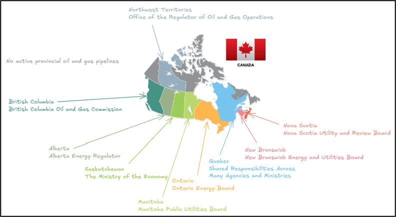
In Canada, pipelines that cross interprovincial, interterritorial, or international borders are federally regulated; intra-provincial or intra-territorial pipelines are regulated by the provincial or territorial regulator. All federally regulated onshore pipelines must comply with CSA Z662 as per the Onshore Pipeline Regulations (OPR/SOR-99). In general, all provinces and territories also require the use of CSA Z662. However, there is variation regarding whether the standard is explicitly required or included by reference.
CSA Z662 includes ten sections and a variety of informative annexes. This article will concentrate on Section 10, which is Operating, Maintenance and Upgrading, with a specific focus on assessing pipeline imperfections per CSA Z662. CSA Z662 uses the terminology of “imperfection” to describe a feature that has been discovered, typically by some inspection method, but has not yet been shown to be potentially deleterious. Section 10.10 describes the assessment of imperfections, and it is stated that if an imperfection is not acceptable per Section 10.10, it shall be considered a defect. A defect is defined as “an imperfection of sufficient magnitude to warrant rejection based upon the requirements [of CSA Z662].” Any imperfections that are determined to be defects require repair using one of the acceptable methods listed in CSA Z662. The required timeline for repair implementation depends on the nature of the repair and the damage. Typically, the operating company submits a proposed repair plan to the Canadian Energy Regulator (CER), who approves the repair plan and timeline.
CSA Z662 Section 10.10 includes reference to the following imperfections:
- Corrosion imperfections
- Arc burns and gouges
- Dents
- Pipe body surface cracks
- Weld imperfections in field circumferential welds
- Weld imperfections in mill seam welds and mill circumferential welds
- Ripples, wrinkles, and buckles in pipe
Aside from arc burns and gouges, which CSA Z662 classifies as defects without distinction, all other imperfections can be assessed using high-level methods from Section 10.10 or using an engineering assessment.
CSA Z662 Section 10 Assessment
Section 10 of CSA Z662 provides high-level assessments for imperfection corrosion, ripples, wrinkles and buckles, and dent imperfections. For corrosion, there is an assessment threshold that requires no calculation effort. All corrosion imperfections are considered acceptable provided the exclusive internal and external corrosion results in a wall loss of less than 10% of the nominal thickness and the imperfections are not coincident with a crack.
If the corrosion imperfection being assessed is not acceptable based on this initial limit, there is a secondary assessment limit based on simple calculations. Section 10 stipulates that a corrosion imperfection deeper than 10% and not co-located with a dent or crack is acceptable, provided it is not longer than what is provided in ASME B31G, if it complies with the 0.85dL method or the effective area method. Note that the 0.85dL method is otherwise called the modified B31G method, and the effective area method encompasses a variety of methods including RSTRENG and the P-squared method. If the corrosion imperfection is not considered acceptable based on these secondary criteria, an engineering assessment can be performed to determine if it shall be considered a defect.
The Section 10 assessment for ripples, wrinkles and buckles, or dent imperfections is laid out differently than for corrosion imperfections. While the corrosion imperfection assessment per Section 10 provides methods for calculating whether corrosion is a defect, the ripples, wrinkles and buckles, and dent assessment states all ripples, wrinkles and buckles, and dents are considered defects unless they meet a certain list of criteria. The list of criteria for ripples and wrinkles and buckles includes a variety of limitations on dimensions of the imperfection based on the pipeline type and operating stress level. The list of criteria for dents includes limitations on depth, forming strain based on local curvature, coincidence with other imperfections such as corrosion or cracks, and susceptibility to fatigue loading. If the ripple, wrinkle and buckle, or dent has any of the features in the Section 10 list, it can either be designated as a defect or evaluated using an engineering assessment.
For pipe body cracks and weld imperfections in mill welds, Section 10 does not provide any evaluation; it simply states that pipe body cracks and imperfections in mill welds with sizes beyond what is considered acceptable based on non-destructive testing are considered defects unless otherwise determined by an engineering assessment. Section 10 also provides no assessment for imperfections in field circumferential welds and requires that imperfections in field circumferential welds are considered defects unless shown to be acceptable based on an engineering critical assessment.
Engineering Assessments
An engineering assessment, as defined in CSA Z662, is an assessment based upon engineering principles that evaluates and documents the effects of relevant variables on the fitness-for-service or integrity of a pipeline. Although this article discusses engineering assessment in light of imperfection assessment, CSA Z662 allows engineering assessment for certain aspects of design, evaluations during fabrication, and for other operational adjustments such as new pipeline crossings or class location changes.
The process for performing an engineering assessment is described in CSA Z662 Section 3.4. CSA Z662 requires operating companies to develop a process for performing engineering assessments. The goal of this requirement is to ensure engineering assessments are consistent and that the responsibilities and competencies of those performing the engineering assessment are clear and the methodologies used in the assessment are documented. Within this documentation requirement, CSA Z662 also includes a suggestion to classify engineering assessments and base requirements for competency and methodologies. A system of Level 1, Level 2, and Level 3 is recommended, where Level 1 includes simple assessments that rely on screening criteria and require a competent technical person within the operating company, and Level 3 includes complex assessments that may utilize emerging methodologies and require the competency of a subject matter expert.
When an engineering assessment is completed, according to CSA Z662, the records associated with the assessment must be kept for the life of the pipeline.
Regarding the allowable methods that can be used for an engineering assessment, CSA Z662 does not provide any specific requirements. CSA Z662 is intended to be a performance-based rather than prescriptive standard. As such, the only guidance on acceptable methods is that they should employ good engineering practices. Provided the methodology used is an industry-accepted practice or approach and the engineering assessment is performed by a competent individual, it is acceptable per CSA Z662.
Engineering Critical Assessments
CSA Z662 also, confusingly, refers to engineering critical assessments (ECAs). These differ from engineering assessments in that an ECA applies to the evaluation of crack-like imperfections or cracks specifically in circumferential non-mill welds, and an engineering assessment applies to everything else.
Annex J of CSA Z662 provides a recommended practice for performing ECAs of crack-like imperfections in fusion welds. Annex J states that the principles of fracture mechanics shall be used in determining the maximum tolerable size for imperfections. It states that while other methods may be used, the recommended method for performing an ECA is provided in CSA Z662 Annex K.
Annex K provides standards of acceptability for circumferential pipe butt welds based upon fracture mechanics principles. The annex itself is informative rather than mandatory. For linear imperfections (i.e., crack-like imperfections), Annex K provides two options for assessment.
Option 1 provides two equations, one for maximum tolerable imperfection size to avoid failure by brittle fracture and one to avoid failure by plastic failure (also called plastic collapse or overload). Option 1 does not directly address the potential for failure by a mix of brittle and plastic collapse. The equation for assessing brittle fracture is based upon the methods presented in BSI PD 6493 Guidance for Assessing the Acceptability of Flaws in Fusion Welded Structures. (PD 6493 has since been replaced with BS 7910 Fracture and Fatigue Assessment.) The equation for assessing plastic collapse is based on the Miller solution, which is a limit-state solution for cracked cylinders. The implementation of the Miller solution in Annex K was modified by work performed by the Pipeline Research Council International (PRCI).
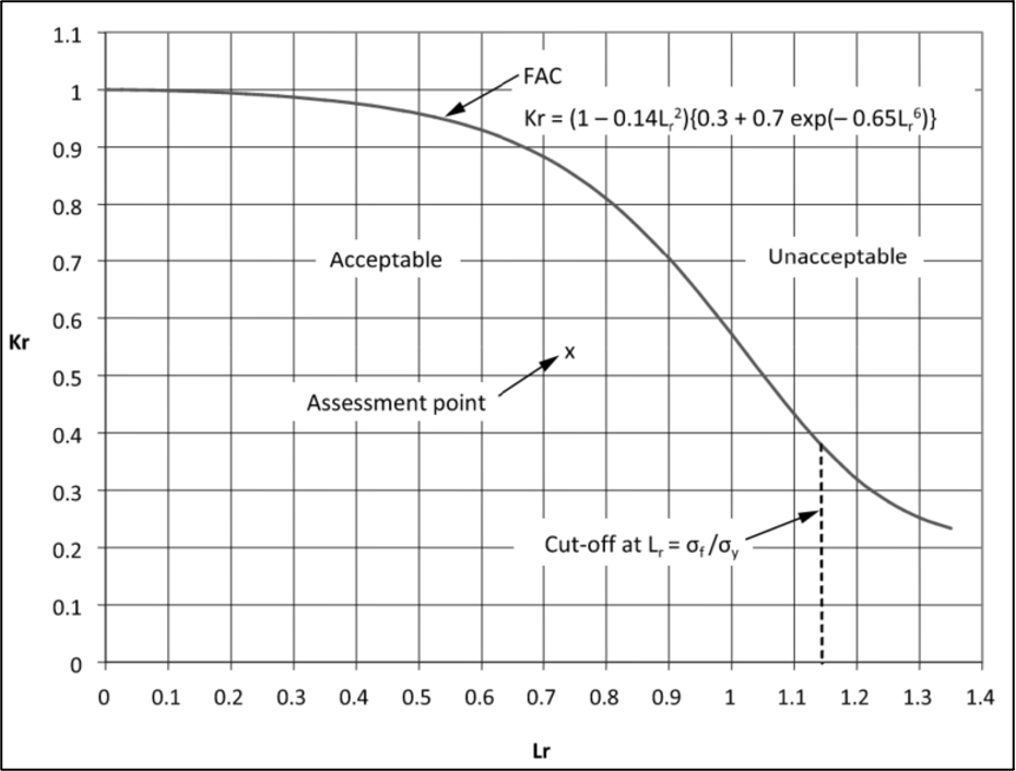
Option 2 uses a failure assessment diagram (FAD) approach, similar to Part 9 of ASME FFS-1/API 579-1 (API 579) or BS 7910. In fact, the equation that defines the failure assessment curve (FAC) is the same as shown in API 579. The FAC is shown in Figure 2. An interesting difference between the Annex K Option 2 approach and the API 579 FAD approach is that Annex K requires, or at least prefers, using CTOD testing to determine the fracture toughness used to calculate the FAD assessment point. Additionally, while API 579 provides two annexes of stress intensity and reference stress solutions for a variety of different loadings, geometries, and imperfection orientations, Annex K provides only one stress intensity solution and one reference stress solution.
Based on information provided in the annex, the solutions are applicable only to surface-breaking, circumferentially oriented crack-like imperfections. Users should be aware that the reference stress and stress intensity solutions provided in Annex K should not be used for longitudinally oriented imperfections or for imperfections located in areas where the pipe geometry cannot be represented by a cylinder (e.g., at a branch connection, at a tee, near a support, etc.). To perform an ECA for these types of crack-like imperfections, methods beyond Annex K such as API 579, BS 7910, CORLAS, and others should be used.
Two other interesting points regarding the ECA methods presented in Annex K are that, according to the annex, no determination of weld residual stress is required, and there is no explicit consideration for fatigue crack growth. Residual stress considerations are not included because a 1983 study showed that residual stress had an insignificant effect on the strain applied at failure of the imperfection.
Regarding fatigue crack growth, Annex K is only applicable if the imperfection has a depth less than 50% of the nominal wall thickness for gas pipelines and less than 25% for liquid pipelines. Supposedly, these maximum depths were chosen such that all imperfections analyzed with Annex K will have a stress intensity factor below the threshold stress intensity range for fatigue crack growth. The annex does not provide a reference for determining that imperfections less than 50% nominal thickness for gas and 25% for liquids have stress intensity ranges that are not susceptible to fatigue crack growth.
While Annex K provides the recommended ECA method per CSA Z662, other methods are acceptable and can be applied provided they demonstrate good engineering judgement and are performed by competent individuals.
Summary
CSA Z662 is a comprehensive Canadian standard that supports pipeline integrity management across the full lifecycle of a pipeline. The standard is mandated for federally regulated pipelines and adopted for provincial and territorial pipelines. While CSA Z662 does provide some guidance on assessing corrosion, dents and ripples, and wrinkle and buckle imperfections found in service, it guides the user to perform engineering assessments or ECAs that employ good engineering practices. While the standard doesn’t provide specific requirements as to how these assessments should be performed, it does provide requirements for the documentation of the assessments, competencies of those performing the assessments, and record retention. It is important for pipeline operators and consulting firms working in the Canadian pipelines industry to understand these requirements and ensure all assessments related to the integrity management of Canadian pipelines adhere to them.