Up until the recent publication of ASME SBS-2023: Structures for Bulk Solids (ASME SBS), there has not been a comprehensive American standard for the design and construction of metallic structures containing bulk solids. Guidance within American standards had been limited to concrete silos with documents such as ACI 313 or focused on specific bulk solids applications. European Code EN 1991-4 provides a comprehensive approach to metallic silos, and now ASME SBS offers similar guidance in the United States.
This article will give a brief introduction to the ASME SBS document and concepts for bulk solids storage.
Documentation Outline
| Section 1 – General Requirements | Discusses scope of the document & responsibilities |
| Section 2 – References | |
| Section 3 – Definitions | |
| Section 4 – Materials | Lists allowable certified materials (plates, forgings, castings, structural members, and fasteners) and requirements for gaskets and sealants. |
| Section 5 – Loadings Imposed by Bulk Solids | Provides calculations to obtain loads imposed by the bulk solids as a function of container geometry and bulks solids material properties. |
| Section 6 – Design | Provides weld joint design requirements and load considerations as well as design rules for shells, openings, roofs, anchorage, and hoppers. |
| Section 7 – Fabrication | Stipulates fabrication/alignment tolerances, limits on forming strain, welding requirements, joint efficiency rules, and post-weld heat treatment requirements. |
| Section 8 – Examination & Testing | Specifies examination requirements (radiography, ultrasonic, magnetic particle, liquid penetrant, visual) and load testing requirements. |
| Section 9 – Overpressure Protection Venting | Provides requirements for overpressure and deflagration protection. |
Loading Considerations
Loading considerations for structures include typical structural loads such as dead, live, internal/external pressure, seismic, snow, and wind loads. Unique to bulk solids structures, loading considerations also include bulk solids loads which are detailed in Section 5 of ASME SBS. Section 5 provides procedures to calculate loads on the following components:
- Vertical container walls
- Slender containers
- Squat and intermediate slenderness containers
- Retaining containers
- Hopper walls
- Steep hoppers
- Shallow hoppers
- Flat bottom containers
- Additional considerations for mass flow loads
- Additional considerations for solids with entrained gases and fluidized solids
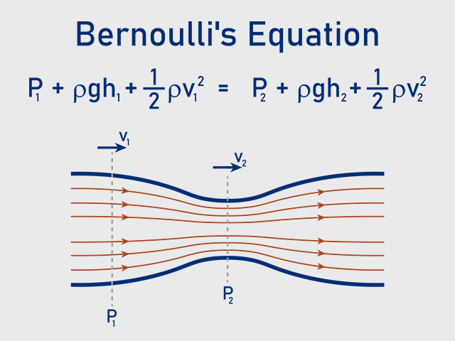
Unlike hydrostatic pressure that occurs in liquid storage structures such as tanks and pressure vessels, bulk solids loading does not only exert a pressure load normal to the shell wall. Due to the friction of the bulk solid acting on the wall, the solids also exert shear load on the shell wall acting downward in the direction of gravity—that is, liquid hydrostatic pressure can be considered isotropic, with pressure acting equally in all directions at a given depth, while bulk solid pressure can be considered anisotropic, having different magnitudes dependent on direction.
Additionally, liquid hydrostatic pressure, Ph,liquid, acts linearly as a function of height:

Where,
ρ = Mass density of the fluid
g = Gravitational acceleration
h = Liquid fill height
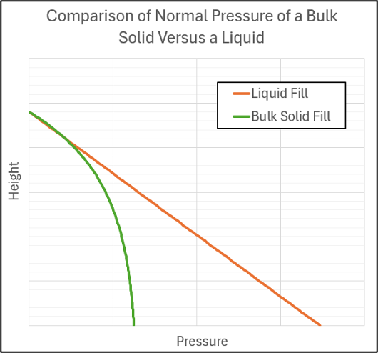
The normal pressure generated by bulk solids is nonlinear. As the column of solids increases, so do the frictional forces generated within the column and between the solids and the structure’s walls. This results in asymptotic behavior of the normal pressure curve as a function of fill height. The formula used to calculate the normal pressure is referred to as the Janssen equation and has the general form:

Where,
Pb = Bulk density of the solid
g = Gravitational acceleration
b = Hydraulic radius of the structure
k = Lateral pressure ratio
μ = Wall friction coefficient
h = Fill height
D = Diameter of the structure
Using the Janssen equation, normal pressure can be plotted as a function of height as shown in the figure below. The figure also compares the pressure distribution to a linear distribution which would be caused by liquid fill.
The shear pressure acting on the shell can be calculated by multiplying the normal pressure by the coefficient of friction between the bulk solid and the shell wall. This shear loading and the exponential behavior of pressures in bulk solids storage containers are fundamental concepts unique to bulk solids which are not currently covered in typical pressure vessel codes. Section 5 of ASME SBS employs a form of the Janssen equation to estimate loads on silo walls and hoppers. The procedures have limitations on silo geometry, stored solids, and filling/discharge arrangements.
Ultimately, the calculations are highly sensitive to the bulk solids material properties such as bulk density, lateral pressure ratio, angle of internal friction, and coefficient of wall friction. Therefore, Section 5 requires that ranges of material properties be used in the calculations. The ranges of properties are the responsibility of the end user and are ideally obtained through material testing at the expected handling conditions (such as temperature and moisture content). ASME SBS provides typical properties for well-known bulk solids in Nonmandatory Appendix D, which are permitted for use in lieu of testing.
General Design Requirements
ASME SBS employs an allowable stress design basis, where the allowable tensile stress for plates is the minimum of 2/3 the yield stress of the material or 40% of the ultimate tensile strength of the material.
The design thickness of welded containers is determined by ensuring the sum of the hoop stress (divided by the joint efficiency) and vertical compressive stress is less than the allowable stress of the material. Section 6 also provides rules for designing cylindrical shell containers subjected to vertical compressive loading and external pressure due to wind and vacuum pressure. If the rules for external pressure of Section 6 are not satisfied, ASME SBS permits the external pressure rules of ASME BPVC Section VIII, Division 1 (ASME VIII-1) to be used.
Section 6 also provides design rules for self-supporting or rafter-supported cone, spherical, and umbrella dome roofs. Elliptical and flanged-and-dished roofs are also permitted if conforming to the rules of ASME VIII-1 paragraph UG-32. Design rules are provided for both internal and external pressure designs including considerations for rafter buckling, rafter bracing, and roof-to-shell reinforcement (including compression rings).
Anchorage design is also covered within Section 6 of ASME SBS. Containers can be considered self-anchored if the resisting dead load exceeds the total equivalent vertical load due to wind or seismic load. Otherwise, the container requires anchorage and anchor rods which may be sized per the requirements of ACI 318 or AISC 360 for the anchor rod loads calculated per Section 6.
ASME SBS Appendices
Mandatory Appendix I of ASME SBS provides design recommendations for foundations and includes guidelines for the design and construction of foundation systems. The requirements outlined in the appendix include requirements for geotechnical reporting, design, construction tolerances, inspection, and testing.
The following nonmandatory appendices are also included within ASME SBS:
- Nonmandatory Appendix A – Coatings and Linings
- Coatings/linings for abrasion and corrosion protection
- Linings for flow promotion
- Coating/lining selection guidance
- Surface preparation
- Coating application
- Inspection
- Repair
- Safety considerations
- Nonmandatory Appendix B – Bulk Solids Storage Containers Data Sheet
- Mechanical and physical properties of contained product
- Operating conditions
- Environmental conditions
- Fabrication and construction requirements
- Materials of construction
- Nozzle design data and operating loads
- Nonmandatory Appendix C – Flow Patterns
- Describes flow patterns (mass flow vs. funnel flow) and typical attributes
- Provides design charts to achieve mass flow
- Nonmandatory Appendix D – Bulk Solids Properties
- Provides typical bulk solids properties for well-known bulk solids
- Includes a default material to be assumed in lieu of testing but cautions that the material may not be applicable for small installations and could result in cost-ineffective designs for large silos
Case Study
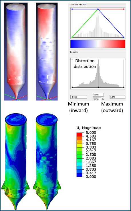
Distortion in the cylindrical shell of a silo was identified. Due to concerns that the distortion could impact the structural capacity of the silo, an engineering evaluation of the silo was performed to quantify the remaining strength of the silo shell. The evaluation consisted of obtaining laser scan data of the silo shell, mapping the data onto a finite element model, and simulating the anticipated loads in the finite element analysis (FEA) to demonstrate that the silo has adequate protection against relevant failure mechanisms. The following figure shows the laser scan distortion data and the representative distortion mapped onto the FEA model.
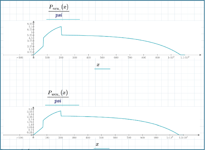
Once the distortion is mapped on the model, loads acting on the silo are simulated up to the appropriate load factors. Loading considered in the model includes weight, internal/external pressure, wind, and bulk solids loading. The analysis was completed prior to the release of ASME SBS, so the bulk solids loading was characterized in accordance with EN 1991-4 which is consistent with the methodology of ASME SBS. The loading due to the stored solids includes normal pressure acting on the silo and hopper walls as well as a shear load acting downward on the silo and hopper walls due to the friction between the stored solids and the walls. Plots of the normal (top) and shear (bottom) pressures are shown below.
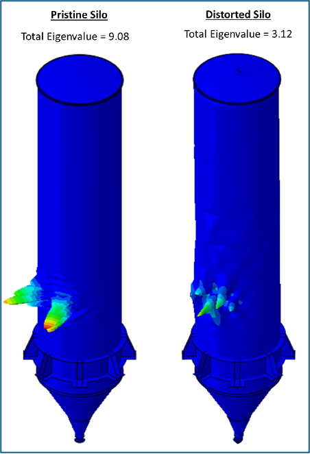
All relevant failure mechanisms are assessed per Annex 2D of API 579. The primary failure mechanism of concern is buckling. To demonstrate adequate protection against buckling, a limit load analysis is performed on the distorted geometry utilizing a Type 2 buckling assessment per Part 5 of ASME VIII-2. Note that the analysis was conducted prior to the release of the 2025 Edition of ASME VIII-2 which includes updated buckling rules in Part 5. The Type 2 buckling assessment consists of an eigenvalue analysis and comparing the calculated eigenvalue to the nominal loads, incorporating a safety factor of 1.67.
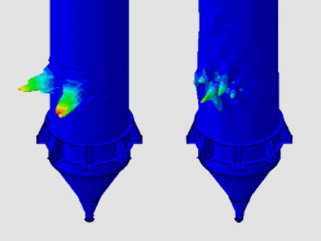
The results of the analysis indicate that the predicted eigenvalue is greater than the required value (including safety factor), indicating the silo is adequately protected against buckling. A plot of the predicted eigenmodes (for the pristine and distorted silo geometry) is shown below.
In conclusion, ASME SBS now offers a comprehensive design methodology for metallic silos. Specifically, the document includes procedures for estimating the loading of the stored solids on the silo which can be leveraged in fitness-for-service assessments as demonstrated in the presented case study.