1. Introduction
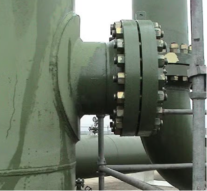
Bolted flange joints are critical components in pressure vessels and piping systems, with widespread usage in refineries, power plants, and chemical process industries. Ensuring their integrity under applied loading is vital for safety, leak prevention, and asset reliability. The assembly and assessment of bolted flanged joints are governed by both ASME standards and site-specific Engineering Practices (EPs), which together rigorously influence joint integrity. The following discussion expands upon key design and operational considerations, drawing from codes and standards as well as Equity’s experience in assessing bolted joints.
2. Bolted Flanged Joint Components and Assembly
A bolted flange joint consists of three primary elements: the flanges, the bolts or studs, and the gasket. Each plays a distinct role:
- Flanges (typically per ASME B16.5/B16.47 or custom-designed): Provide the structural surface for sealing and fastener mounting
- Bolts/Nuts or Studs (e.g., ASTM A193/A194): Provide clamp force to seal the joint
- Gasket (e.g., spiral wound, sheet, PTFE): Provides the compliant seal between flange faces
2.1. Joint Selection
- Flange Type: Based on pressure class, temperature, cyclic load, and alignment. Weld neck flanges are generally preferred for their superior strength and reliability.
- Gasket Selection: Dependent on process fluid, pressure, temperature, and flange geometry. Chemical compatibility and compressive load requirements are critical considerations for gasket specification and selection.
2.2. Assembly Practices
- Bolt Lubrication: Reduces friction, ensuring uniform preload across all bolts. Best practices are to clean and liberally lubricate threads and nut faces. When establishing an assembly procedure, the nut factor (K) for the specific lubricant should be considered, as this varies based on lubricant type and manufacturer.
- Tightening Sequence: Star pattern or spiral outwards prevents tilting and uneven gasket load.
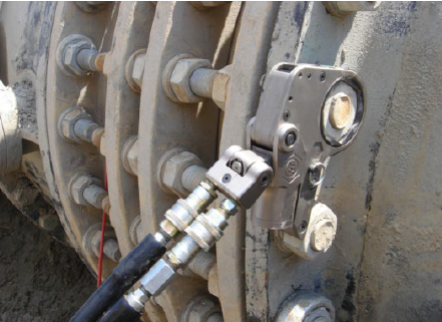
- Torque Application: Use calibrated torque wrenches; for critical joints (typically with large diameter bolts/studs), hydraulic tensioners may be specified. Accuracy of applied bolt load generally increases by method from manual torque (lowest accuracy) to hydraulic torque to hydraulic tensioning (highest accuracy). Other methods such as use of tension control fasteners and ultrasonic bolt length measurement may be employed for critical joints to improve accuracy, but come with added cost, complexity, and/or operator training requirements.
3. Bolt Stress: Determination and Control
3.1. Bolt Stress Fundamentals
Bolt stress quantifies the mechanical integrity and sealing effectiveness of the joint during both assembly and operational conditions. Accurately controlling bolt stress is essential; it must be high enough to sufficiently seat and compress the gasket but must remain below the material’s yield and creep thresholds, especially in elevated temperature environments.
Traditionally, bolt stress is evaluated by:

Where:
- δbolt = Bolt stress
- Fpreload = Applied preload force during assembly
- Abolt,eff = Effective cross-sectional area of the bolt, net of any threads or reductions
3.2. Compliance with ASME Code
ASME BPVC Section VIII, Division 1 (ASME VIII-1) Appendix 2, which as of the 2025 edition references the design procedure in ASME BPVC Section VIII, Division 2 (ASME VIII-1) Part 4.16, prescribes stress requirements for various gasket types and ensures that bolt stress and flange stresses (at assembly and in service) remain below specified allowable values:
- Seating Stress: Ensures initial gasket seating
- Operating Stress: Maintains seal under pressure, accommodates relaxation
3.3. Bolt Load Determination
Bolt load must account for:
- Gasket seating load (based on minimum gasket stress)
- Internal pressure acting on the effective gasket area
- External loads (e.g., piping-induced moments, structural loads)
- Thermal transients (which induce bolt stress due to differential expansion/contraction)
Simplified design formula for operating bolt load based on ASME code:
Ftotal,bolt = (gasket seating area) x (gasket seating stress)
+ (pressure area) x (internal pressure) + (external/thermal loads)
3.4. Bolt Materials & Elevated Temperature
High-temperature applications demand bolts with elevated yield strength and creep resistance—often ASTM A193-B16 or alloy materials considering creep effects for service above 800°F (425°C). For uninsulated flanges, the bolting can typically be considered to be 80% of the fluid temperature, or even lower if heat transfer calculations are performed to demonstrate further reduction of bolt temperatures.
3.5. Bolt Relaxation and Retightening
Bolts relax due to:
- Embedment: Flattening or flow at flange faces, gasket, and threads after initial tightening
- Creep: Time-dependent plastic deformation, accelerated at elevated temperature
- Gasket flow: Settling or compression loss in gasket over time
Regular inspection and retightening intervals help maintain integrity, especially in critical connections and hot service. It should be noted that hot torquing after start-up may be effective, but after any significant period of operation, the lubricant degrades and torque application is not a reliable means to achieve required bolt load. If joint tightening is required after a period of operation, using a turn-of-nut procedure is needed to ensure reliable additional bolt load is added.
4. Gasket Stress and Leak Prevention
4.1. Gasket Material Response
Gasket integrity relies on achieving a controlled compressive load across its effective area. The gasket must be sufficiently compressed to produce an initial seal on bolt-up that resists the process fluid’s pressure, temperature, and dynamic loads and maintains a seal; however, excess compression can crush or extrude the gasket, leading to joint failure. Each gasket type—spiral wound, sheet, PTFE, metallic, or semi-metallic—has established minimum seating stress (required on bolt-up) and minimum sealing stress (lower value required to maintain seal in operation after initial seating) requirements and maximum allowable compressive stress, which is typically available from gasket vendors, established in company best practices, and/or codified in standards such as ASME B16.20/B16.21. Additionally, percentage of bolt load loss (or relaxation) can be a function of the gasket material properties that should be considered. It should be noted that these gasket stress values can vary significantly even for the same gasket type depending on gasket manufacturer, so users should employ caution when applying generic values for a given gasket type or assuming a specific vendor’s stress values are applicable to all gaskets of the same general type.
4.2. Gasket Stress Calculation
Gasket stress is the applied compressive force distributed over the gasket’s effective sealing area:
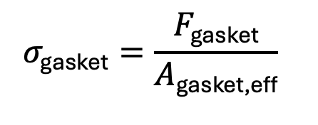
Where:
- δgasket = Gasket compressive stress
- Fgasket = Clamp load transmitted through the gasket
- Agasket,eff = Effective sealing area, commonly calculated as the mean circumference times gasket width
This compressive stress must meet three requirements during joint design and assembly:
- Seating Stress (y): Minimum preload at installation required to deform and seat the gasket, ensuring initial tightness
- Operating Stress (m ⋅ P): Additional load to maintain the seal under internal pressure, where m is the gasket factor and P is the design pressure
- Maximum Allowable Stress: Not to be exceeded, preventing crushing or blowout of the gasket
4.3. Leak Prevention: Assembly and FEA-Driven Analysis
Traditional design methods (ASME VIII-1 Appendix 2, ASME VIII-2 Part 4.16) provide minimum design requirements for seating and service stresses but do not explicitly address leak risk or gasket opening under actual bolt loading or combined thermal and mechanical loads. ASME PCC-1 Appendix O and Welding Research Council Bulletin 538 (WRC 538) provide methodology for addressing such conditions, and commercial software such as Equity Software’s® IntelliJoint® provide options to assess troublesome joints and optimize gasket selection and bolting procedures, but there are limits of applicability to weld neck flanges or those that can be approximated as weld neck flanges with flat gaskets entirely inside the bolt circle, as well as limitations in loading scenarios that can be assessed in such an assessment.
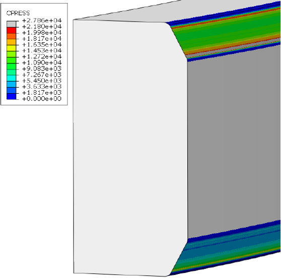
Advanced finite element analysis (FEA), particularly axisymmetric contact modeling, offers critical capabilities for leak prevention:
- Nonlinear Gasket Modeling: FEA incorporates realistic gasket behavior by using experimentally measured stress-strain and compressibility curves. This allows simulation of gasket response under incremental loading, accurately predicting both seating stress and potential separation during pressure or thermal cycles.
- Contact and Separation Prediction: Through nonlinear contact elements, FEA detects the onset of flange opening or loss of compression across any part of the gasket, directly representing leak-prone conditions that code equations cannot capture.
- Combined Load Analysis: FEA can simultaneously apply bolt preload, pressure, and temperature gradients, showing how these interact to influence gasket stress, flange rotation, and long-term seal integrity.
- Bolted Joint Geometries: Behavior of ring joint flanges, reverse flanges, lip seal flanges, etc. that cannot be adequately approximated as weld neck flanges can be accurately modeled in FEA.
4.4. Influence of Gasket Geometry and Face Type
Gasket width and face geometry significantly affect the required seating load and leakage risk:
- Wider gaskets demand higher clamp force but can offer better impermeability, provided the flange’s bolt pattern supports adequate loading. For robust flanges where flange damage or excessive rotation is not a concern, wider gaskets can achieve a more reliable seal. In the opposite case where the flanges cannot handle higher bolt loads without damage or rotation, use of a narrower gasket may be the best option to achieve adequate gasket stress for a reliable seal.
- Raised face, ring-type joint (RTJ), or tongue-and-groove flanges influence the stress profile and contact pressure distribution; FEA can resolve these nuances across the joint section and identify local regions prone to separation or under- or over-compression.
- Gasket selection, width, and style should be tailored for process fluid compatibility, operating pressure/temperature, and assembly practices, referencing site EPs for compliance.
4.5. Best Practices for Leak Prevention
- Always use controlled, calibrated torquing or hydraulic tensioning to apply uniform bolt load.
- Apply quality lubrication to threads and nut faces to ensure true bolt stress is achieved.
- Follow specified tightening sequence and re-torque protocols to mitigate gasket relaxation and embedment loss.
- For critical or high-risk applications, validate designs with FEA incorporating nonlinear gasket data and contact mechanics, especially for non-standard or high-temperature joints.
5. Flange Strength Determination
Flange designs must resist gross plastic deformation and maintain joint stiffness to prevent excessive gasket rotation or opening. This affects not only the structural integrity of the flange itself, but also the reliability of the gasket seal under operational loading.
5.1. ASME VIII-1 Appendix 2 / ASME VIII-2 Part 4.16 Approach
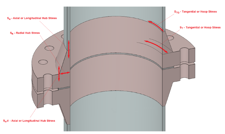
Traditional calculations (beam and ring theory) focus on sectional stresses—at the hub, bore, and bolt circle. ASME prescribes allowable stress criteria for flange material (bending, axial, hoop), but these methods rely on geometric simplification and often under-represent the complexity of real assembly and field conditions.
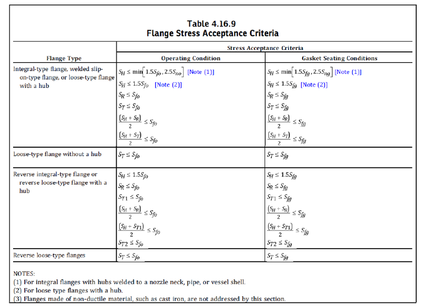
WRC 538 modifies this design procedure and uses similar formulation to calculate flange stresses, but resets limits to a function of material yield strength based on a parametric FEA study of weld neck flanges. This provides more useful limits for flanges based on actual bolt loads, which commonly exceed the allowable bolt stress (1/5th of ultimate tensile strength) per the ASME design calculations.
5.2. Advanced Finite Element Analysis (FEA) for Flanged Joints
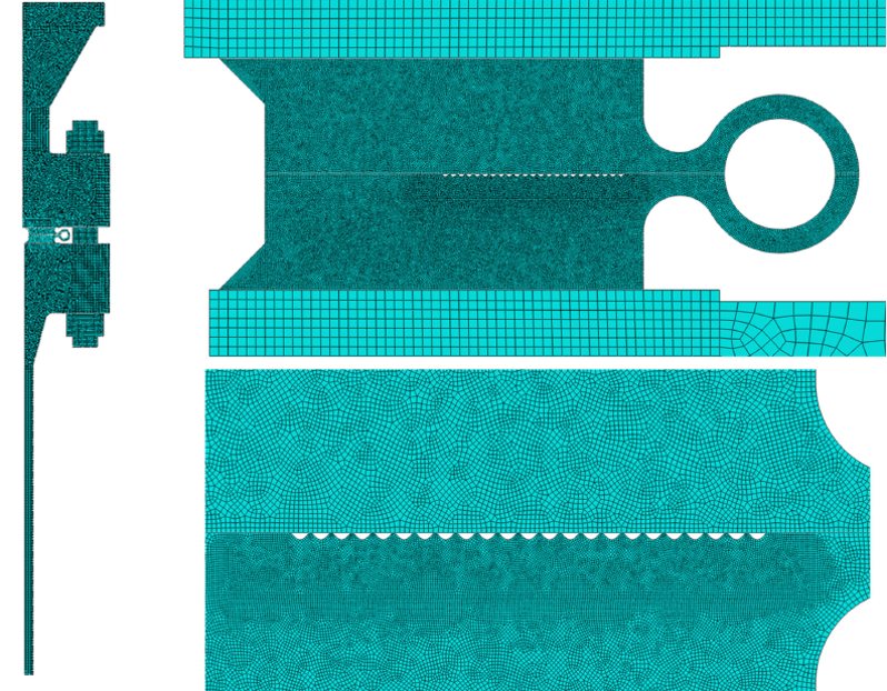
For non-standard flanges and where more nuanced loading or material configurations exist, axisymmetric or 2D FEA provides detailed, high-fidelity mapping of stress and strain throughout the flange, hub, gasket, and bolts. In some cases, further detailed 3D FEA may be required to capture non-symmetric loading or stress/strain distributions, effects of individual bolts, etc.
- Advantages Over Traditional Methods
FEA captures full-field stress distributions and incorporates boundary conditions such as combined mechanical, pressure, and thermal loads, as well as assembly effects (loading sequences, gasket seating, and bolt relaxation). Nonlinear gasket compression and opening are directly modeled, enabling more reliable predictions of leak risk and gross flange separation that are not possible with ASME VIII’s simplified design methods or IntelliJoint assessments. - When Axisymmetric FEA is Preferred
Axisymmetric FEA is particularly effective for joints with uniform bolt sizes and preloads, as well as symmetric pressure and temperature profiles. It supports rapid design iterations and delivers good accuracy in clamp load, stress, and leakage risk estimation, while offering computational savings compared to full 3D analysis.
Caution: Axisymmetric FEA is not appropriate for highly asymmetrical loading (eccentric forces, severe thermal gradients), nor for joints with very few bolts or irregular layouts; these conditions may require full 3D modeling for accuracy.
- Modeling Details: Bolt and Flange Representation
- Bolts/Studs: In axisymmetric FEA, bolts are represented as annular rings with solid elements (e.g., ABAQUS CAX4, CAX8). For simplified (plane stress) 2D analyses, bolt cross-sections are modeled as rectangles using ABAQUS CPS4 or CPS8. ABAQUS-specific methods allow non-uniform “plane stress thickness” to mimic real bolt/nut geometry and local stiffness.
- Anisotropy Due to Bolt Holes: Rather than explicitly modeling bolt holes (which disrupt symmetry), the flange region at the bolt circle is assigned anisotropic material properties—radial and axial elastic moduli are reduced according to the fractional area lost to holes, with circumferential modulus set low to capture compliance.
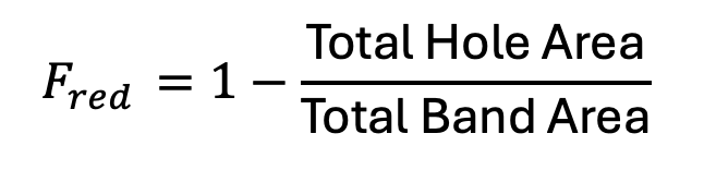
Where, F is the area reduction factor applied to the modulus.
- Radial and axial modulus: Er = Ea = E x Fred
- Circumferential modulus: Ec is set to a very small fraction of E
- Stress Concentration: Axisymmetric models approximate average stiffness loss; local peak stresses between holes require 3D FEA.
5.3. Flange Representation in FEA
- Bolt Hole Effects
The reduction in circumferential area and stiffness in the bolt circle is ‘smeared’ circumferentially in 2D FEA by assigning engineering constant material properties with local orientation. Contact between the bolt hole inner diameter and the stud is not explicitly modeled in axisymmetric setups; full 3D models may be warranted for cases of significant flange rotation or local contact.
- Mesh Refinement
The bolt hole band and gasket interface require mesh refinement in FEA to accurately resolve stress gradients. Defining element sets for each stud and flange region expedites selection and analysis.
5.4. Implications for Leak and Strength Prediction
- FEA enables direct assessment of gasket separation and compression under realistic assembly and field loading.
- Peak local stresses, gross opening, and leak risk can be evaluated more fully than is possible by code equations or more simplified spreadsheet or software approaches.
6. Joint Integrity: Factors and Best Practices
6.1. Initial Assembly Integrity
Achieving robust joint integrity begins during assembly. Use of proper lubrication on bolt threads and nut faces is critical for minimizing friction and ensuring uniform preload across all bolts. Bolts should be tightened using manufacturer-recommended or otherwise engineered torque values, applied sequentially in a star or spiral-out pattern to avoid uneven gasket compression and flange tilting. Engineering analysis is specifically recommended for joints with a history of leakage or for critical services to optimize assembly procedures and reduce the likelihood of leakage.
For high-pressure or critical service, hydraulic tensioning is recommended for precise preload application. These steps collectively help establish a reliable joint with minimal risk of initial leak, embedment loss, or bolt relaxation.
6.2. In-Service Integrity and Inspection
Joint integrity must be continuously monitored after assembly to prevent leakage or catastrophic failure. Key inspection activities include:
- Gasket Leak Checks: Regular visual and acoustic inspection for signs of seal leakage
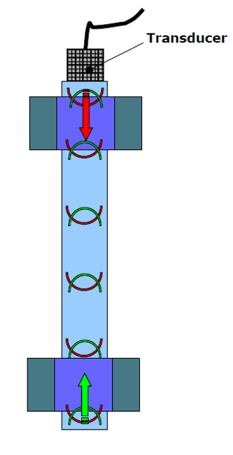
- Bolt and Nut Condition: Verifying bolt tension using ultrasonic methods or strain gauges (especially in critical applications), while visually inspecting for corrosion, stretch, or thread galling
- Flange Assessment: Monitoring for signs of flange rotation, separation, or opening—key indicators of loss of clamp load or excessive bending
- Cyclic Loading and Vibration: Pipes subject to vibration or dynamic loads should be supported using braces or struts, particularly at large-radius bends, to prevent transfer of bending moments to the flange joint
Maintaining joint integrity requires a lifecycle approach, including written inspection schedules, periodic re-torqueing, and retraining of assembly personnel. Joints exposed to high vibration, thermal cycling, or frequent maintenance should be flagged for enhanced monitoring and, where warranted, engineering analysis that may include advanced FEA techniques.
If you have any questions for the authors, you can submit the form below: