Key Takeaways:
- Damage characterization drives repair strategy. Identifying the damage mechanism — not just its physical appearance — determines which repair methods are viable, which codes apply, and where else in the system to look for similar damage.
- Always perform an FFS assessment before committing to repair. Not every inspection finding requires physical intervention. An FFS screening per API 579-1/ASME FFS-1 confirms whether damage actually exceeds acceptable limits and frequently eliminates unnecessary repair scope.
- Repair and alteration are distinct classifications with different requirements. A repair restores equipment to its existing design conditions. An alteration changes them. Misclassifying an alteration as a repair is one of the most common compliance gaps found during mechanical integrity audits.
- Engage the Authorized Inspector before finalizing the repair approach. The AI certifies that repair work meets jurisdictional requirements. Completing work without prior AI concurrence risks having to redo it entirely.
- A repair that does not address root cause will fail again. Selecting a technically correct repair method is not sufficient if the underlying damage mechanism has not been resolved. Root cause determination is a required step, not an optional preliminary.
Every piece of process equipment degrades in service. Corrosion thins walls, fatigue initiates cracks at weld toes, and erosion removes material at flow disturbances. How a repair is planned and executed when damage is found determines whether equipment returns to safe, reliable service or develops a new problem on a shorter timeline.
For early-career engineers, the repair process is one of the most cross-disciplinary areas of practice. Inspection engineers characterize the damage. Mechanical engineers develop the repair strategy. Welding engineers qualify the procedures. Materials engineers evaluate metallurgical compatibility. Project engineers coordinate execution. Understanding how those roles connect, and what each one requires, is foundational to working effectively in any of them.
How Does the Repair Process Work?
Step 1: Damage Discovery and Characterization
Damage is typically found through scheduled inspection, in-service leakage, or a process upset that triggers investigation. Before any repair work begins, the damage must be fully characterized: type, location, dimensions, and the operating and design conditions of the affected component. Damage characterization determines which repair options are viable, which codes govern the work, and whether additional inspection is needed to bound the extent of damage.
Damage type is particularly important. Localized corrosion, stress corrosion cracking (SCC), fatigue, and erosion-corrosion are distinct mechanisms that respond differently to the same repair method. A repair approach appropriate for wall thinning from general corrosion is often wrong for an environment-assisted cracking problem.
Step 2: Extent of Condition
Finding damage in one location raises a predictable follow-up question: where else does it exist? The damage mechanism indicates which other components in the system are susceptible. A piping circuit with internal corrosion in one spool has a credible probability of similar damage elsewhere in the same service. Defining the full extent of condition before committing to a repair scope prevents the common and costly scenario of completing a repair and immediately finding adjacent damage that requires additional outage time.
Step 3: Identify the Construction Code
Every pressure-containing component was fabricated to a construction code: ASME Section VIII, Division 1 or Division 2 for pressure vessels, ASME B31.3 for process piping, API 650 for atmospheric storage tanks, and others. That code of record must be identified before repair planning begins, because the repair must be executed in a manner consistent with it and with the governing in-service inspection code.
The code of record is normally documented on the nameplate or Manufacturer’s Data Report. Missing or incomplete records require recovery or reconstruction before the repair can proceed, which adds significant time and cost to what might otherwise be a routine scope.
Step 4: Determine Jurisdiction and Governing Documents
Construction codes were written primarily for fabrication, not in-service repair, and do not provide comprehensive guidance for repair work. The documents that govern repair work are the applicable in-service inspection code (API 510 for pressure vessels, API 570 for piping, API 653 for atmospheric storage tanks) and, for pressure vessels in many jurisdictions, the National Board Inspection Code (NBIC NB-23), which is incorporated into state boiler and pressure vessel laws throughout much of the United States. NB-23 Part 3 specifies procedural requirements for repairs and alterations in detail. It is critical to understand the jurisdictional requirements with respect to acceptable methods for engineering evaluations, repairs, and alterations prior to proceeding with a run/repair/replace strategy.
The Authorized Inspector (AI) is the individual who represents the jurisdiction and certifies that repair work meets code requirements. The AI makes the final determination on acceptability. Engaging the AI before the repair approach is finalized is not a procedural courtesy; it is a practical necessity. Repair work that does not have AI concurrence before execution may need to be redone entirely.
Step 5: Fitness-for-Service Assessment (Run, Repair, or Replace?)
Before initiating repair, the engineer should confirm that repair is actually required. If the damage is within the limits established by the applicable fitness-for-service (FFS) standard, the equipment may be acceptable for continued operation without intervention. This determination is made through an FFS assessment per API 579-1/ASME FFS-1, which provides a structured, quantitative basis for the run-repair-replace decision.
FFS assessments are organized into three levels of increasing analytical rigor. Level 1 uses screening criteria and is accessible to inspectors or engineers with working knowledge of the standard. Level 2 involves more detailed calculations and does not always require specialized software, though some damage types at Level 2 are complex enough that most engineers use it. Level 3 requires advanced techniques such as finite element analysis (FEA). Most day-to-day repair screening work falls at Level 1 or Level 2.
Skipping this step and defaulting directly to repair is a common and avoidable error. FFS screening takes time, but it frequently reveals that equipment is within acceptable limits, eliminating unnecessary repair scope, outage time, and cost. FFS can also be used to optimize a repair strategy. For example, a large area of metal loss may not require complete weld metal buildup back to nominal thickness, reducing scope of repair in a short turnaround and extending life until a more extensive repair or replacement can be planned for and performed at a more suitable time in the future.
Step 6: Develop and Execute the Repair Strategy
The primary reference for repair methods is ASME PCC-2, Repair of Pressure Equipment and Piping. The table below summarizes common repair methods, their typical applications, and key limitations.
| Repair Method | Typical Application | Key Limitations and Notes |
| Weld buildup / overlay | External buildup to restore wall thinned by internal corrosion | Not permitted where cracking is present. Post-weld cleaning and interpass temperature control are critical for alloy materials. |
| Flaw excavation and weld repair | Removal and repair of surface or embedded flaws exceeding code allowances | Excavation may be left unrepaired if FFS assessment confirms acceptability of remaining geometry. |
| Insert plate | Replacement of a locally damaged shell section with new plate material | Often the most direct permanent repair for localized vessel shell damage. Requires full weld joint inspection. |
| Full encirclement sleeve | Structural reinforcement or pressure boundary restoration on damaged pipe sections | Type A: structural only (ends not welded to pipe). Type B: pressure-retaining. Type B is not addressed by NBIC and requires jurisdictional approval in many cases. Sleeves are not typically suitable or allowed as repair for crack-like flaws. |
| Composite wrap | Reinforcement of corroded or thinned piping where weld repairs are impractical | May be permanent or temporary depending on the specific PCC-2 article, service conditions, and repair design. Not appropriate for cracking, high-temperature service, or where the corrosion source has not been addressed. |
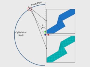
| Fillet-welded lap-patch repair | Temporary reinforcement/repair of locally damaged shell section | Easier repair than insert plate and can be done in-service, but several considerations needed for design and implementation. Not addressed by NBIC and requires jurisdictional approval in many cases. |
Method selection requires understanding the damage mechanism, the service environment, and the long-term intent for the equipment. A repair that addresses visible damage without correcting its underlying cause will fail again. All repair welding must be performed under a qualified Welding Procedure Specification (WPS) by a qualified welder. Using the wrong procedure introduces residual stresses, heat-affected zone (HAZ) concerns, and potential new flaws that can be worse than the original condition.
Step 7: NDE and Pressure or Leak Testing
Completion of welding does not close out the repair. NDE is required to verify repair quality and confirm that no new flaws have been introduced. The required NDE method and coverage depend on the governing repair standard and the type of repair performed.
Post-repair pressure or leak testing is typically required as well. Where hydrostatic testing is impractical due to brittle fracture risk, system isolation constraints, or other factors, alternatives including pneumatic testing and NDE substitution are available under PCC-2 Article 502. Any deviation from standard pressure test requirements must be planned in advance and accepted by the AI.
Repair vs. Alteration: An Important Distinction
These terms have specific technical and regulatory meanings, and misclassifying one as the other has real consequences for documentation requirements and AI oversight.
| Repair | Alteration | |
| Definition | Restores equipment to a condition suitable for continued service at existing design conditions | Changes design conditions, configuration, or rated capacity of the equipment |
| Examples | Weld overlay on thinned shell, insert plate, sleeve repair on damaged nozzle | Adding a nozzle, increasing MAWP, changing service fluid, modifying structural supports |
| Engineering review | Confirm repair restores compliance with existing design basis | Full re-evaluation of affected components against current design conditions; may require new calculations and updated code stamp |
| AI involvement | Required; AI certifies repair compliance | Required; typically more extensive review and documentation than for repairs |
A common error is executing what is functionally an alteration under the classification of a repair. If process conditions have changed and equipment was never re-rated, a seemingly routine nozzle addition or shell modification may constitute an alteration under the applicable in-service code. When the classification is not clear, confirming with the AI before starting work is the right approach.
What Does This Look Like in Practice? (Case Study)
Background
During a routine turnaround at a processing facility, inspection of a pressure vessel revealed significant pitting and localized wall thinning concentrated along weld seams. The base metal in adjacent areas was largely undamaged, indicating that the corrosion was concentrated in the weld HAZ rather than reflecting general service degradation.
Initial Repair and Repeat Failure
The initial repair used a high-alloy weld overlay with a higher pitting resistance than the original filler material. After returning to service, new pitting appeared within months at the boundaries between the original welds and the repair welds — the repair had not held.
Root Cause Investigation
Metallurgical investigation identified two contributing causes. First, the original welds had experienced intermetallic precipitation in the HAZ from insufficient heat control during fabrication, producing chromium-depleted areas preferentially attacked by the process fluid. Second, post-weld cleaning after both the original fabrication and the subsequent repair had been inadequate. The heat-tinted oxidation layer was not fully removed, which prevented proper passivation and directly reduced the corrosion resistance of the material at those locations.
Corrective Approach
The corrective repair combined the appropriate corrosion-resistant weld overlay filler with strict interpass temperature controls and thorough post-weld cleaning to restore the passive oxide film. Both root causes were addressed in a single repair scope rather than treating the visible pitting in isolation.
Key Takeaway
The initial repair failed not because the method was wrong, but because it addressed the symptom without resolving the underlying mechanism. This is a recurring pattern in pressure equipment repair work: a technically correct procedure applied to an incompletely diagnosed problem will produce a technically correct failure. Root cause determination is not a preliminary step that can be skipped when the damage appears straightforward.
What Do New Engineers Get Wrong?
Skipping the FFS assessment
Not every inspection finding requires physical repair. An FFS screening per API 579 is a standard step before committing to repair scope, and it frequently demonstrates that equipment is within acceptable limits. Moving directly to repair planning without this step adds cost and outage time that may be entirely unnecessary. While FFS does not eliminate the damage mechanism, it can be used to demonstrate safe continued operation until a future time that allows for planned repairs or replacement.
Treating repair methods as interchangeable
Repair method selection is not a matter of convenience or availability. Each method in ASME PCC-2 has defined applicability conditions and explicit exclusions. A composite wrap is unsuitable for a cracking mechanism, high-temperature service, or any situation where the corrosion source has not been addressed. Selecting a method without confirming it is appropriate for the specific damage type and service environment is a common source of repair failures.
Underestimating in-field welding requirements
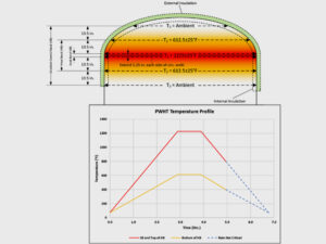
Field repair welding is technically more demanding than shop fabrication. The base metal has service history, potential contamination, and existing residual stresses. Preheat, interpass temperature control, hydrogen management, and post-weld heat treatment (PWHT) all become more consequential in this context. PWHT in the field is often impractical, and while there are code-recognized alternatives, those alternatives have defined limitations and should not be applied without a welding or materials expert confirming their suitability.
Not engaging the Authorized Inspector early
The AI certifies that repair work satisfies jurisdictional requirements. Completing a repair without prior AI concurrence creates a real risk that the work will not be accepted, requiring rework or, in some cases, removal and replacement. The AI should be involved from the beginning of repair planning, not at the end of execution.
Misclassifying temporary repairs
Composite wraps, temporary clamps, and similar methods are classified as temporary repairs in the governing standards. They are appropriate interim measures while permanent repairs are engineered and scheduled, not long-term solutions. Temporary repairs that are never resolved are a routine finding in mechanical integrity audits and represent a gap in the facility’s equipment management program.
What Should I Learn Next?
- ASME PCC-2: The articles on specific repair methods, particularly weld overlay, flaw excavation, full encirclement sleeves, and alternatives to PWHT, provide the technical grounding needed for day-to-day repair and alteration work.
- API 510, API 570, and API 653 repair sections: These in-service codes are the primary reference documents for repair and alteration requirements in most process facilities. Familiarity with their repair sections is practical from the start.
- NBIC NB-23 Part 3: Essential for engineers working in facilities subject to NBIC jurisdictional requirements for boilers and/or pressure vessels. It covers repair and alteration procedures in detail and is frequently cited by Authorized Inspectors.
- ASME Section IX: Weld procedure qualification underpins all repair welding. Understanding the structure of a WPS, procedure qualification record (PQR), and welder performance qualification gives engineers the ability to evaluate whether the welding program supporting a repair is adequate.
- API 579-1/ASME FFS-1: Level 1 and Level 2 assessments are a direct companion to repair work. Being able to screen damage against FFS acceptance criteria independently is one of the most immediately applicable skills to develop in this space.
Closing Thoughts
Pressure equipment repair involves inspection findings, code requirements, materials behavior, welding practice, and operational constraints. The seven-step process outlined here provides a framework, but executing it well requires judgment at every step: understanding what the damage is telling you, selecting methods that address the underlying mechanism, and working within the procedural structure that keeps the work defensible and code-compliant. For a new engineer, the highest-value habits to develop early are confirming root cause before selecting a repair method, engaging the AI before committing to an approach, and treating documentation as an integral part of the repair rather than a closeout task.
Please submit any questions via the form below:
Frequently Asked Questions
What is the difference between a repair and an alteration on a pressure vessel?
A repair restores equipment to its original design conditions without changing rated capacity, configuration, or design intent. An alteration changes one or more of those parameters: adding a nozzle, modifying support structure, or increasing the maximum allowable working pressure, for example. A change in service fluid does not automatically constitute an alteration; if the new service remains within existing design conditions, it may require a management-of-change (MOC) review without triggering formal alteration classification. Alterations require a full engineering re-evaluation and typically involve more extensive documentation and Authorized Inspector oversight than repairs. Misclassifying an alteration as a repair is a common compliance gap found during mechanical integrity audits.
What codes govern pressure vessel and piping repairs in the United States?
Repair work on pressure vessels is typically governed by API 510, and, in many jurisdictions, NBIC NB-23 Part 3. Piping repairs fall under API 570 (NBIC NB-23 only applies for specific boiler external piping situations, not process piping). The specific repair procedures and accepted methods are detailed in ASME PCC-2. Jurisdictional requirements vary by state; some states reference NBIC directly through their boiler and pressure vessel laws, while others defer to API standards. The Authorized Inspector assigned to the facility is the right starting point for confirming which documents apply.
When is an FFS assessment required before repairing equipment?
An FFS assessment is not always a regulatory requirement before repair, but it is sound engineering practice and a recognized pathway under in-service codes such as API 510 and API 570. An FFS assessment per API 579-1/ASME FFS-1 determines whether damaged equipment is structurally adequate for continued operation within its current design conditions. If the assessment confirms acceptability, repair may not be needed at all. Skipping this step and defaulting to repair without establishing whether the damage exceeds code-acceptable limits adds unnecessary cost and outage time.
What is the role of the Authorized Inspector in a pressure equipment repair?
The Authorized Inspector (AI) represents the jurisdiction and is responsible for certifying that repair work has been performed in accordance with the applicable codes and standards. In practice, the AI reviews the repair plan, witnesses or accepts the required NDE and pressure testing, and signs off on the repair documentation. In jurisdictions governed by NBIC, no repair is considered complete without AI concurrence. Engaging the AI at the beginning of repair planning rather than at the end of execution is strongly advisable; repairs completed without prior AI involvement may not be accepted, requiring rework.
What is ASME PCC-2 and when does it apply?
ASME PCC-2, Repair of Pressure Equipment and Piping, is the primary standard for in-service repair methods across pressure vessels, piping, and related equipment. It is organized into articles covering specific techniques including weld overlay, flaw excavation and weld repair, full encirclement sleeves, insert plates, composite wraps, and alternatives to post-weld heat treatment. PCC-2 is referenced by API 510, API 570, and NBIC NB-23, and is the document most often consulted when developing a repair procedure. Each article specifies applicability conditions and explicit limitations, making method selection a code-governed decision rather than a matter of field judgment alone.