Process facility owner-users understandably focus on maintenance of pressure vessels, piping, storage tanks, and other assets critical to the production of their product. Often overlooked in the overall asset management strategy is the structural infrastructure that supports production. While some of these systems can be treated as typical building-type structures from a design, analysis, and maintenance perspective, things get a bit more interesting where structural infrastructure and pressure boundary components intersect. The required function of these structural systems differs from typical civil engineering applications, necessitating forms that present unique challenges. This article will walk through several case studies of structural engineering applications in process facilities to demonstrate how these problems can be solved through an understanding of both structural and mechanical systems.
Qualifying a Reactor Bed for Increased Pressure Differential
Reactor vessels are critical to many operations. Catalyst beds within these reactors are often supported through beams running across the inside of the reactor that support a grid or perforated floor for holding catalyst. In addition to weight, these structures must withstand a differential pressure (DP) across the bed. Operating conditions and/or fouling of the bed over time tend to increase this DP, potentially exceeding the original design limit. Support beams often have non-standard materials and shapes relative to typical structural engineering applications, making them difficult to assess. Pressure vessel design handbooks offer some methods of design but often neglect relevant buckling responses, potentially resulting in unconservative designs.
Equity Engineering was recently asked to qualify a catalyst bed for continued operation at higher DP. The bed had historically operated at DP of about 15 psig but significantly increased to about 70 psig. The owner targeted 80 psig as the desired limit for the bed. Equity Engineering assessed the bed and recommended modifications needed to achieve this load with sufficient margin.
Design By Analysis of Vessel Internals
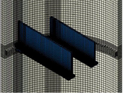
The bed featured four beams constructed from built-up T-sections of stainless-steel material. The tees were oriented upside down with grid bars spanning between the flanges. A finite element analysis (FEA) model depicting the beams and shell is shown in Figure 1 (grid bars not shown). The beams feature a notched end and two blocks welded to the tee web that sit on a ledge around the inside perimeter of the reactor wall, as shown in Figure 2.
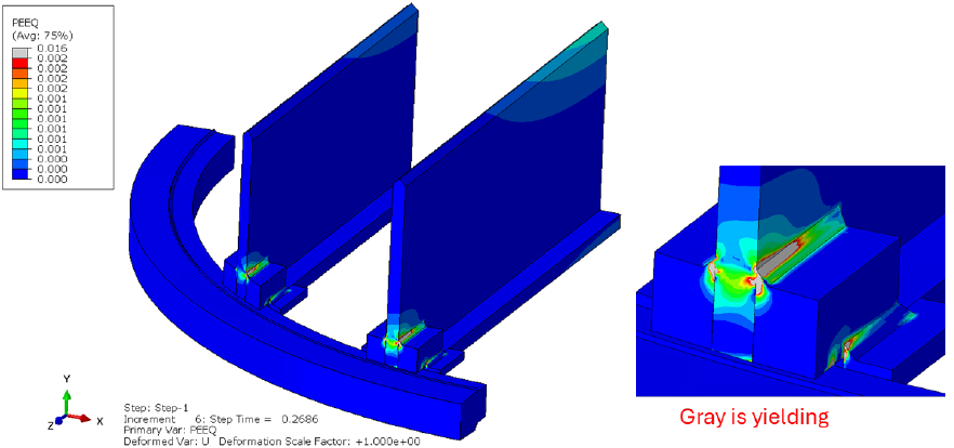
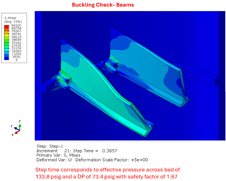
Hand calculations were first performed to assess the structure using AISC 325/360 and AISC Design Guide 27 for stainless-steel structures. These calculations indicated that the beam end weld detail was severely inadequate for the target DP, while all other components appeared acceptable. However, given the stainless-steel material and non-standard beam cross section and loading, the beam capacity results were questionable. Equity Engineering hypothesized that a design-by-analysis approach per ASME VIII-2 Part 5 would provide significant improvement in the connection capacity over hand calculations due to the significant ductility of stainless-steel material. This evaluation was then performed and showed approximately twice the connection capacity compared to hand calculations but still less than the required 80 psig. Further complicating matters, the beams were found to undergo lateral torsional buckling (LTB) at 73.4 psig (including a 1.67 safety factor on buckling), just short of the 80 psig target as shown in Figure 3.
A Note on Safety Factors
The design-by-analysis approach in this case requires demonstration of protection against plastic collapse, buckling, and local failure (fatigue and creep were not concerns). The general approach is to factor up loads using the target design margin for tensile strength and buckling to assess if the structure can withstand loads at these amplified levels. Reactor internals that are not connected via weld to the pressure boundary governed by the ASME BPVC can be treated as steel structures governed by AISC, which typically uses a 2.0 factor on tensile strength, which is less than typical pressure vessel codes. However, for stainless-steel structures, a 2.7 factor on tensile strength is generally recommended and was considered for this analysis. AISC uses a 1.67 factor on buckling, which is generally consistent with ASME BPVC. Utilizing the reduced factor on tensile strength for vessel internals is critical for qualifying these components. The downside is that separate models are often needed to qualify components with different target margins on tensile strength – in this case, the ledge upon which the beam ends rest.
Modifying the Structure to Improve Capacity
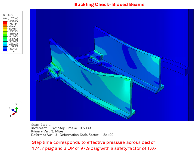
Equity Engineering recommended modifying the beam end connections and installing mid-span bracing at an upcoming opportunity to safely continue operating the reactor. The beam end modification featured a single continuous bearing block slotted through the web instead of one block fillet welded on either side of the web. A steel plate structure was detailed that could slot over the top of all four beams at midspan to effectively brace the LTB action. With these modifications, the model achieved a DP of 97.9 psig, exceeding the 80 psig target. These changes were successfully implemented in the field based on Equity Engineering’s recommendation. The modified structure’s buckling response is shown in Figure 4.
Metal Loss in Storage Sphere Support Legs
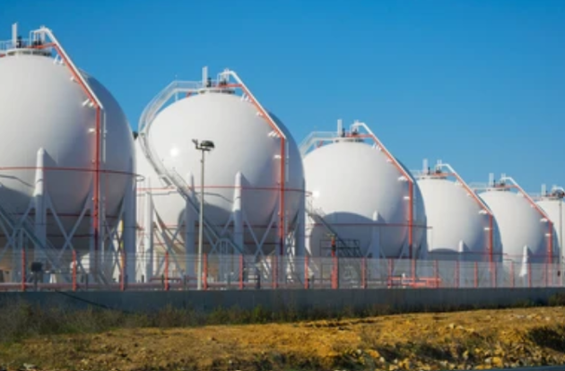
Storage spheres are often supported by a set of legs, often made from circular pipe sections coped to meet the shell and tied together with cross bracing as shown in Figure 5. Metal loss in the legs of these spheres is a common issue; corrosion under insulation (CUI) is the most common mechanism where water infiltrates damaged weather
Balancing Act
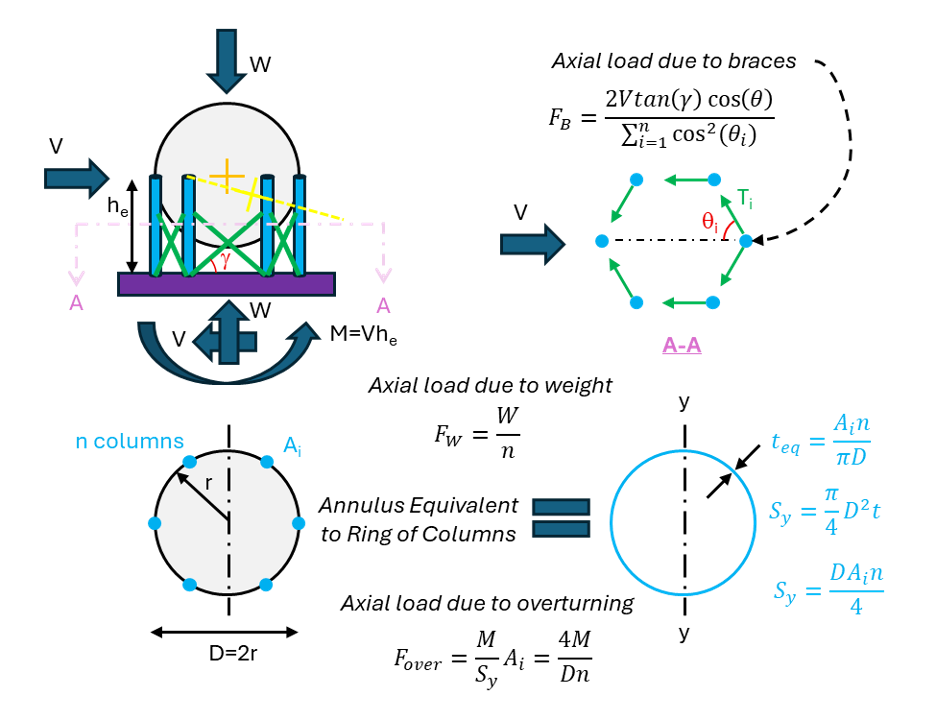
Sphere support legs must support vertical and lateral loads. The primary vertical load is weight, while lateral loads from wind and seismic actions create both a lateral shear and an overturning moment that the columns must collectively resist. Figure 6 shows an illustration of these actions and how they can be apportioned to determine the maximum demand on a given column. Vertical loads can be evenly divided amongst legs and are generally the most significant demand. The ring of columns can be treated as an equivalent annulus of steel with thickness calculated to provide the same total area as the column group. The elastic section modulus can be easily calculated for this section to determine a maximum overturning moment stress. This stress can then be multiplied by the area of one column to determine maximum compressive demand to be added to the weight load.
A third contributor to vertical load comes from the action of cross bracing, which is primarily there to carry lateral shear loads. Taking a free-body diagram cut just below the top of these braces shows how they act when treated as tension-only truss members to resist a lateral load. Thin rods (often pre-tensioned with a turnbuckle) are commonly used for this application, which are highly slender in compression and thus expected to buckle and offer no resistance when not pulled in tension. The axial force carried by a brace is proportional to the angle in the horizontal plane between the brace and the direction of the applied load. These axial forces in each brace include a vertical component due to the inclination of braces. Therefore, when a lateral load is resisted by braces in tension, the braces impart a net axial compressive force on the columns. This force can be calculated as shown in Figure 6 and added with the other vertical loads.
Capacity can be determined using AISC 325/360 to compare with demand. Chapter E for compressive loads is the primary source for calculating strength. Also note the local section slenderness requirements in Chapter B, which can determine if a section is susceptible to local buckling due to slender elements in the cross section (e.g., high D/t ratio for a pipe section). Knockdown factors much be applied for locally slender sections. Column slenderness is typically characterized by the KL/r ratio, where K is an effective length factor, L is the unbraced length, and r is the least radius of gyration of the cross section. Taking K=1.0 is typically conservative and appropriate for sphere support legs. Flexural, shear, and combined load capacities are calculated using Chapters F, G, and H, respectively, all of which can be rearranged to solve for the required thickness.
Devil in the Details
Worth noting is the potential for additional stresses and demands that might require consideration depending on the support design. When legs are coped to meet the shell, there is little to no local eccentricity when axial loads are transferred from the leg to the shell. However, some support designs include an offset between the shell and support leg centroid at the tangent point, resulting in a local eccentricity that creates bending stresses in the leg proportional to the vertical load. Another assumption noted above is that the cross braces are tension-only truss members, which is not always the case, particularly in high seismic areas where stronger braces (e.g., angle sections) are required. These systems do have appreciable compressive capacity and post-buckling residual strength that must be considered to determine the maximum loads on columns. If bracing is absent or damaged, the braces must resist lateral loads via shear, and the vertical length over which these forces are carried can result in a substantial bending moment. Sphere support legs are rarely strong enough to resist lateral loads without bracing; a small amount of steel in the right place can make all the difference.
Determining a Derate Condition and Inspection Interval
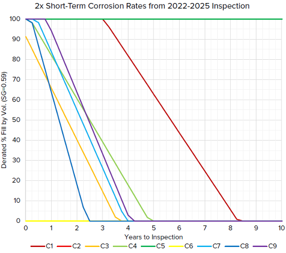
Equity Engineering recently had an opportunity to apply this sphere leg analysis methodology to a vessel with legs experiencing severe and aggressive CUI. Metal loss had already progressed in one leg to the point where it required immediate replacement, and the next worst leg necessitated a derate to about 90% fill by volume. The client wanted to use short-term corrosion rates (CRs) to project each column’s thickness into the future and predict acceptable fill levels as a function of time (or years until the next shutdown and inspection). The goal was to determine a derated fill level and determine when the sphere should be shut down for inspection and likely repair/replacement of multiple legs. Equity Engineering was able to complete this assessment on a rush basis and produce the chart in Figure 7 showing acceptable fill over time for each leg based on their respective CRs. Equity Engineering’s recommendation was a derate to 50% fill by volume for 1 year of operation, which bought the client time to prep for repairs while remaining operational, albeit at significantly reduced capacity.
Conclusion:
The interaction between pressure boundary and structural components presents many engineering challenges. These unique problems often require creative solutions. The multi-disciplinary team at Equity Engineering is well-suited to meet these challenges head-on by combining structural and mechanical knowledge with state-of-the-art technology.
Please send any questions to the author by submitting the form below: